
Fixing device and projector of optical engine

A technology of optical engines and fixtures, used in optics, projection devices, instruments, etc.

Inactive Publication Date: 2013-03-20
SHENZHEN ACTO DIGITAL VIDEO TECH
View PDF3 Cites 0 Cited by
  • Summary
  • Abstract
  • Description
  • Claims
  • Application Information

AI Technical Summary

Problems solved by technology

This ultra-short-throw projection lens is large and heavy, and it is prone to two problems. One is that the lens part is very heavy. During transportation, it is easy to damage the bottom case as long as it is subjected to a slight impact.
Second, because the center of gravity is asymmetrical and the force is unbalanced, the entire optical engine is deformed severely, which causes optical color cast
Aiming at these two problems, the common practice now is to add some buffer pads under the optical engine, or add buffer pads directly in front of the lens. Although this method has played a certain role in protecting the lens, it is not beautiful, and it is also harmful to the lens. Optical color cast doesn't work

Method used


Image

  • Fixing device and projector of optical engine
  • Fixing device and projector of optical engine
  • Fixing device and projector of optical engine

Examples


Embodiment Construction

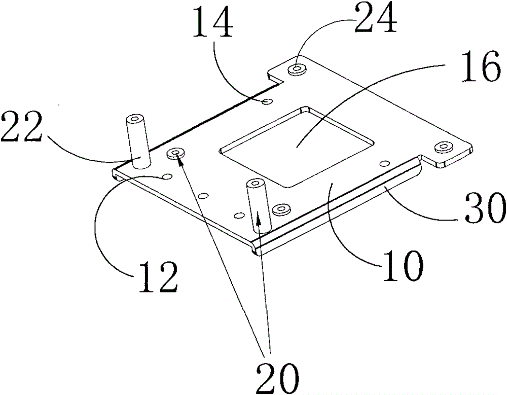
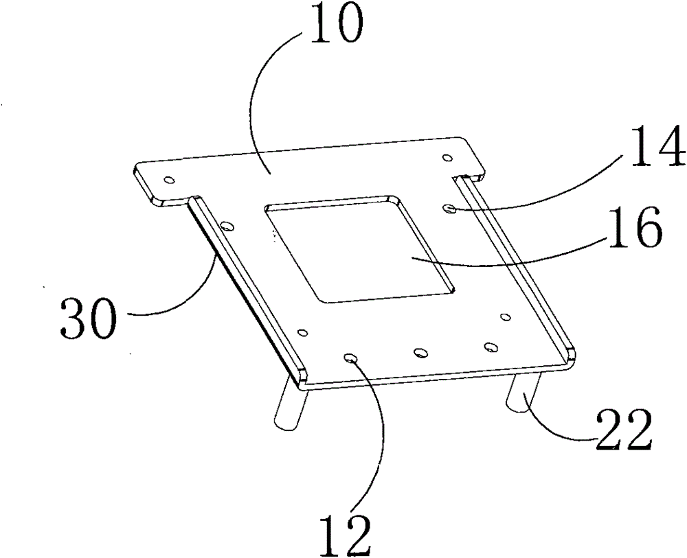
[0019] The substrate 10 is provided with mounting posts 12 and mounting screw holes 14, wherein two mounting posts 12 are provided for positioning during installation of the optical engine fixing device, and 3 mounting screw holes 14 are provided in triangular distribution, and pass through the corresponding Three screws are installed inside the projector housing.

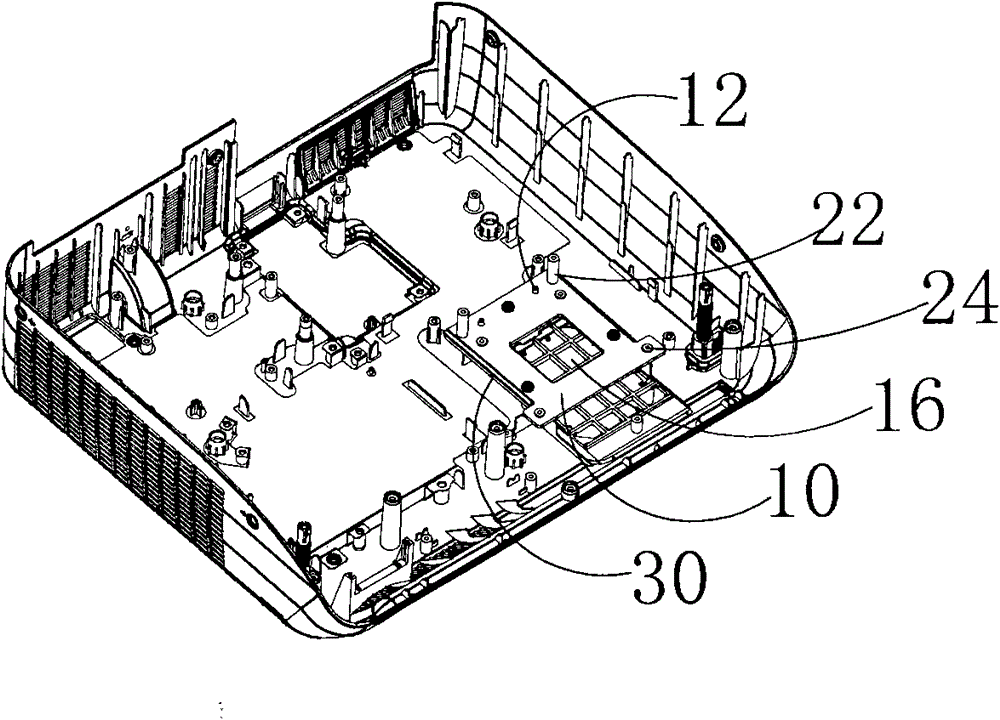
[0020] The studs 20 include elongated studs 22 and flat studs 24 for fixing the optical engine. The folded edges 30 are disposed on both sides of the substrate 10 to enhance the strength of the substrate 10 . Because the two sides of the optical engine fixing device have folded edges for reinforcement, it is difficult to deform in the longitudinal direction, preventing the deformation of the optical engine caused by the deformation of the sheet metal itself.

[0021] like image 3 , Figure 4 As shown, the projector includes a casing 100, an optical engine 200, a liquid crystal panel cooling air duct assembly 30...


PUM


Abstract

The invention discloses a fixing device of an optical engine, which comprises a base plate, studs and hems, wherein the studs are distributed along the edge of the base plate, and the hems are arranged at two sides of the base plate. By adopting the fixing device of the optical engine with the mechanism, because the hems and the splayed studs are in a distributed design, the optical engine can be effectively and fixedly installed, so that the optical engine can not distort easily, thereby effectively reducing optical color cast.

Description

【Technical field】 [0001] The invention relates to a fixing device of an optical engine, in particular to a fixing device of an ultra-short-focus projector and the projector. 【Background technique】 [0002] The ultra-short-throw projectors on the market now are all realized by an ordinary optical engine plus an ultra-short-throw projection lens. This ultra-short-throw projection lens is large and heavy, and it is prone to two problems. One is that the lens part is very heavy. During transportation, as long as it is subjected to a slight impact, it is easy to damage the bottom case. . Second, because of the asymmetrical center of gravity and unbalanced force, the entire optical engine is severely deformed, which causes optical color cast. To solve these two problems, it is common practice to add some buffer pads under the optical engine, or add buffer pads directly in front of the lens. Although this method plays a certain role in the protection of the lens, it is not beaut...

Claims


Application Information

Patent Timeline
Patent Type & Authority Patents(China)
IPC IPC(8): G03B21/14G03B21/16G03B21/00
Inventor 孔祥飞崔凯陈孔锋唐文天
Owner SHENZHEN ACTO DIGITAL VIDEO TECH
Learn More