Wall-in type concealed installation faucet component and installation method

A faucet and component technology, applied in the direction of pipes/pipe joints/pipe fittings, valve devices, water supply devices, etc., can solve the problems of difficult control, unsuitable length of the water outlet adapter exposed to the wall, and difficult installation, etc., to prevent loosening.

Pending Publication Date: 2021-04-23
YUHUAN SHENGLIN COPPER
View PDF1 Cites 0 Cited by
  • Summary
  • Abstract
  • Description
  • Claims
  • Application Information

AI Technical Summary

Problems solved by technology

[0003] The above scheme realizes that the water pipe is buried in the wall, and then the water is directly guided to the washbasin or the sink outside the wall through the wall outlet, so that the faucet and the sink are independent technical requirements, but in the above scheme, there are difficulties in installation. technical issues
In the prior art, the main body embedded in the wall is fixedly installed in the installation groove on the wall. It is difficult to accurately control the position of the main body of the buried wall after installation, and the thickness of the wall decoration is increased after decoration, such as tile layer, cement layer, etc. Difficult to control, especially in the construction of adding decorative surface to the original wall in the second decoration, the length of the water outlet adapter exposed to the wall is not suitable, which makes it difficult to connect the faucet to the water outlet adapter, and it is difficult to realize the effective installation of the faucet

Method used


Image

  • Wall-in type concealed installation faucet component and installation method
  • Wall-in type concealed installation faucet component and installation method
  • Wall-in type concealed installation faucet component and installation method

Examples


Embodiment Construction

[0043] The present invention will be described in further detail below in conjunction with the accompanying drawings and specific embodiments.

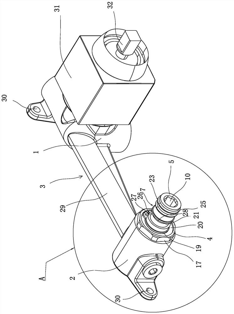
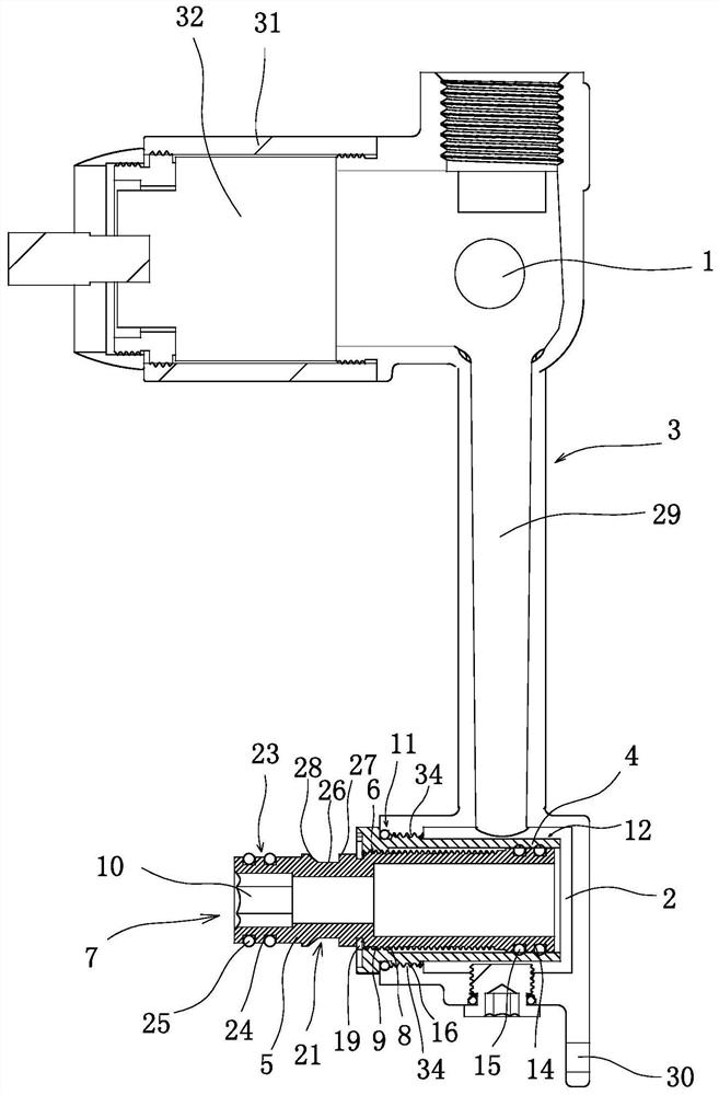
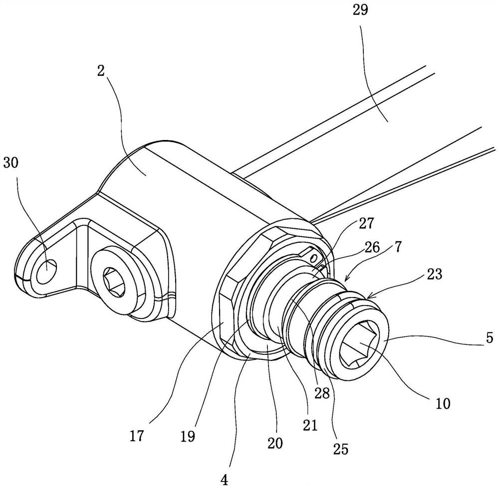
[0044] This in-wall concealed faucet assembly, such as Figure 1-3 As shown, it includes a buried wall main body 3 with a water inlet 1 and a water outlet 2, and a water outlet connecting pipe 4 is detachably fixed on the water outlet 2, and a cylindrical expansion joint is installed inside the water outlet connecting pipe 4. 5. The inner end of the expansion joint 5 is located in the water outlet connection pipe 4, the outer end of the expansion joint 5 is located outside the water outlet connection pipe 4, and the expansion joint 5 and the water outlet connection pipe 4 are provided with energy Adjust the axial relative position of the telescopic joint 5 and the water outlet pipe 4 to adjust the telescopic adjustment structure 6 of the length of the telescopic joint 5 located outside the water outlet pipe 4. The outer end of the tel...


PUM


Abstract

The invention belongs to the technical field of water heating, and particularly relates to a wall-in type concealed installation faucet component and an installation method. The wall-in type concealed installation faucet component comprises a buried wall body with a water inlet and a water outlet, wherein a water outlet connecting pipe is detachably fixed to the water outlet; a cylindrical telescopic joint penetrates through the water outlet connecting pipe; the inner end of the telescopic joint is located in the water outlet connecting pipe; the outer end of the telescopic joint is located outside the water outlet connecting pipe; a telescopic adjusting structure capable of adjusting the axial relative positions of the telescopic joint and the water outlet connecting pipe in order to adjust the length of the part, located outside the water outlet connecting pipe, of the telescopic joint is arranged between the telescopic joint and the water outlet connecting pipe; and a faucet connecting structure is arranged at the outer end of the telescopic joint. According to the wall-in type concealed installation faucet component and the installation method, the strength of the telescopic joint extending out of the wall surface can be adjusted to achieve the advantage of proper faucet installation length.

Description

technical field [0001] The invention belongs to the technical field of hardware and water heating, and relates to a faucet assembly, in particular to a wall-mounted concealed faucet assembly and an installation method. Background technique [0002] The wall-mounted faucet is to bury the water supply pipe in the wall, and then directly guide the water to the washbasin or sink outside the wall through the wall-mounted spout. The faucet and the sink are independent, and the sink does not need to consider how to install it with the faucet. , so there is more design space in the shape, and it is very popular to avoid direct contact with the sink. For example, the Chinese patent document discloses an embedded faucet [201811187368.8], which includes: an embedded box for embedding in the wall and a panel for clamping on the wall surface, the panel and the embedded box are detachable connection; the panel has two openings, and the two openings are respectively equipped with a rotary...

Claims


Application Information

Patent Timeline
Patent Type & Authority Applications(China)
IPC IPC(8): F16L15/02F16L15/04F16K27/00E03C1/02E03C1/042
CPCE03C1/02E03C1/025E03C1/042F16K27/00F16L15/006F16L15/02F16L15/04
Inventor 张雪萍
Owner YUHUAN SHENGLIN COPPER
Why Eureka
Try Eureka