Supercharge Your Innovation With Domain-Expert AI Agents!

Heat exchanger and projector

A heat exchanger and housing technology, applied in the field of projectors, can solve problems such as space filling and achieve the effect of reducing temperature

Active Publication Date: 2010-12-01
SEIKO EPSON CORP
View PDF5 Cites 12 Cited by
  • Summary
  • Abstract
  • Description
  • Claims
  • Application Information

AI Technical Summary

Problems solved by technology

[0008] Therefore, for example, when the projector is installed in an upward projection posture (a posture in which the projection lens is located on the upper side) to project an image upward, or a downward projection posture (a posture in which the projection lens is positioned on the downward side) to project an image downward, air bubbles may spread. The problem that almost the entire space inside the heat exchanger is filled

Method used


Image

  • Heat exchanger and projector
  • Heat exchanger and projector
  • Heat exchanger and projector

Examples


no. 1 approach

[0052] Next, a first embodiment of the present invention will be described based on the drawings.

[0053] (Projector configuration)

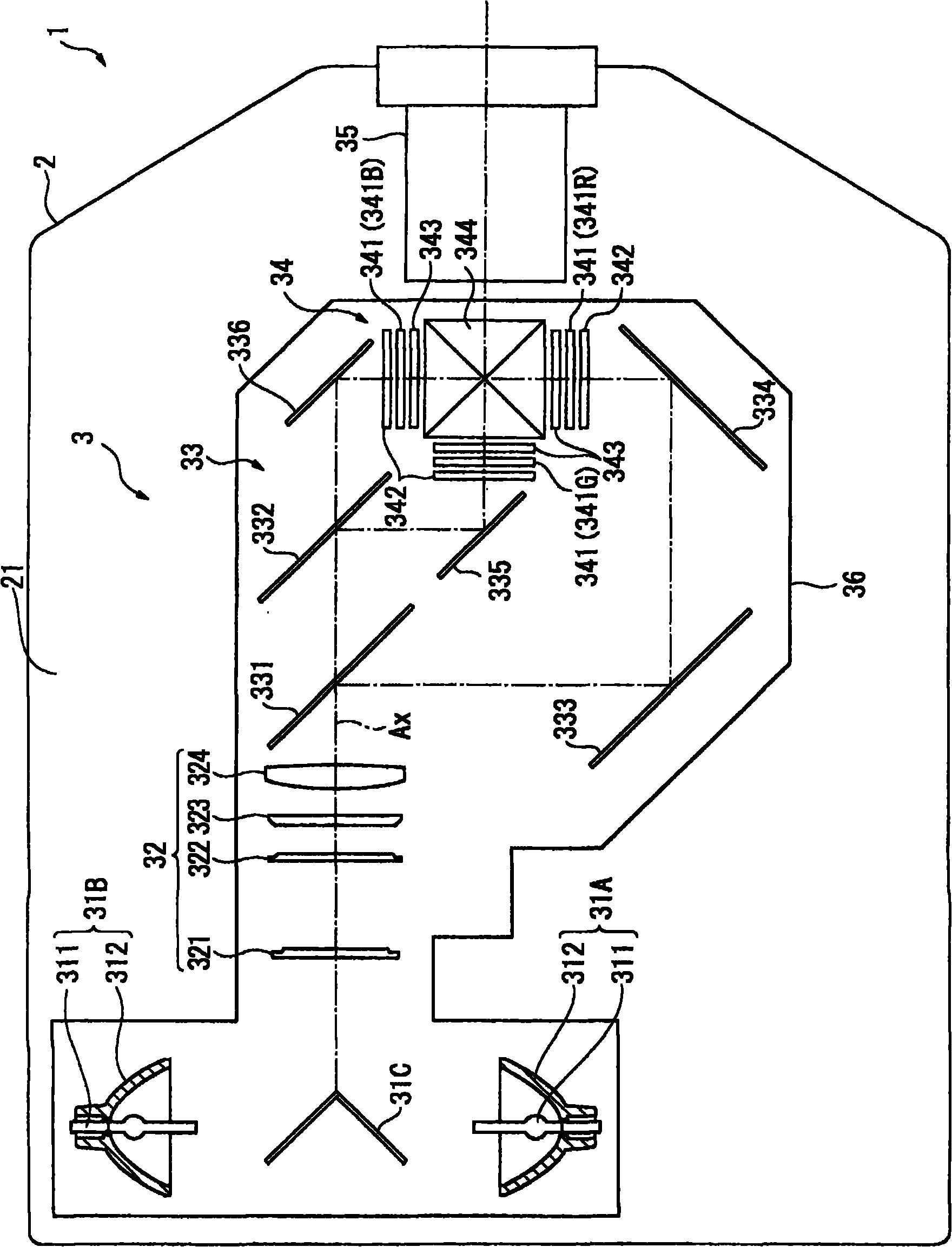
[0054] figure 1 It is a figure which shows the schematic structure of the projector 1 in 1st Embodiment. Specifically, figure 1 from the top surface 21 of the exterior case 2 (refer to Figure 8 ) is a diagram of the internal structure of the projector 1 viewed from the side.

[0055] The projector 1 forms an image corresponding to image information, projects it on a screen (not shown), and displays the projected image. The projector 1 as figure 1 As shown, it includes an exterior case 2, an optical unit 3 and a liquid cooling device 4 (see figure 2 )Wait.

[0056] The exterior case 2 is formed to have a top surface portion 21 intersecting the vertical direction when the projector 1 is installed in an upright posture (refer to Figure 8 ) and the bottom portion 22 ( Figure 8 ) in a substantially rectangular parallelepiped shape, and ...

no. 2 approach

[0157] Next, a second embodiment of the present invention will be described based on the drawings.

[0158] In the following description, the same reference numerals are assigned to the same structures and the same components as those of the first embodiment, and detailed description thereof will be omitted or simplified.

[0159] Figure 10 It is a diagram schematically showing the positional relationship between the projection lens 35 and the heat exchanger 81 in the second embodiment. in particular, Figure 10 It is a figure seen from the top surface part 21 side.

[0160] In this embodiment, if Figure 10 As shown, only the arrangement position of the heat exchanger 81 is different from the first embodiment.

[0161] Specifically, the heat exchanger 81, such as Figure 10 As shown, the shielding plate 81B (+X-axis side) is disposed inside the exterior case 2 in a posture where the shielding plate 81B (+X-axis side) faces the top surface portion 21 side and the +Z-axis...


PUM


Abstract

The invention provides a heat exchanger and a projector, capable of stably keeping the heat exchange efficiency with a cooling liquid and making the air bubble not filled into the approximate whole space inside even though various postures are set. The heat exchanger which is hollow and contains a plurality of small flow paths includes: a plurality of partition walls disposed in parallel with one another in the width direction of the heat exchanger to form the plural small flow paths; and an inlet unit and an outlet unit configured to communicate with the inside and the outside of the heat exchanger, and allow cooling liquid to flow into and out of the heat exchanger through the inlet unit and the outlet unit, the inlet unit and the outlet unit extend in directions opposite to each other along the width direction from a pair of center positions located approximately at the centers of inner side surfaces of the heat exchanger in the width direction and opposed to each other, and penetrate outer side surfaces of the heat exchanger.

Description

technical field [0001] The present invention relates to a heat exchanger for exchanging heat with cooling liquid, and a projector equipped with the heat exchanger. Background technique [0002] It is known that projectors are conventionally equipped with a circulation type liquid cooling device. In order to effectively cool a cooling object such as a liquid crystal panel, the liquid cooling device circulates a cooling liquid along a flow path, and the cooling object is cooled by the circulating cooling liquid. cool down. [0003] In such a liquid cooling device, in order to efficiently cool the object to be cooled by the cooling liquid, a configuration using a heat exchanger for lowering the temperature of the cooling liquid is often adopted (for example, refer to Patent Document 1). [0004] Specifically, the heat exchanger described in Patent Document 1 has a hollow cuboid shape, and an inflow portion and an outflow portion for cooling liquid to flow in and out are respec...

Claims


Application Information

Patent Timeline
Patent Type & Authority Applications(China)
IPC IPC(8): G03B21/16
CPCF28D15/00G03B21/16F28F3/12
Inventor 柳沢佳幸百濑泰长
Owner SEIKO EPSON CORP
Features
  • R&D
  • Intellectual Property
  • Life Sciences
  • Materials
  • Tech Scout
  • Unparalleled Data Quality
  • Higher Quality Content
  • 60% Fewer Hallucinations
Learn More