
Hydrodynamic machine, in particular hydrodynamic retarder

A technology of hydraulic reducer and hydraulic machinery, which is applied in the field of hydraulic machinery and can solve problems such as high cost, high input pressure, cost of funds and power factor

Inactive Publication Date: 2010-12-01
VOITH PATENT GMBH
View PDF0 Cites 4 Cited by
  • Summary
  • Abstract
  • Description
  • Claims
  • Application Information

AI Technical Summary

Problems solved by technology

Here, the high input pressure must be generated cost-prohibitively, and the channel in the center of the torus costs money and power factor λ

Method used


Image

  • Hydrodynamic machine, in particular hydrodynamic retarder
  • Hydrodynamic machine, in particular hydrodynamic retarder
  • Hydrodynamic machine, in particular hydrodynamic retarder

Examples


Embodiment Construction

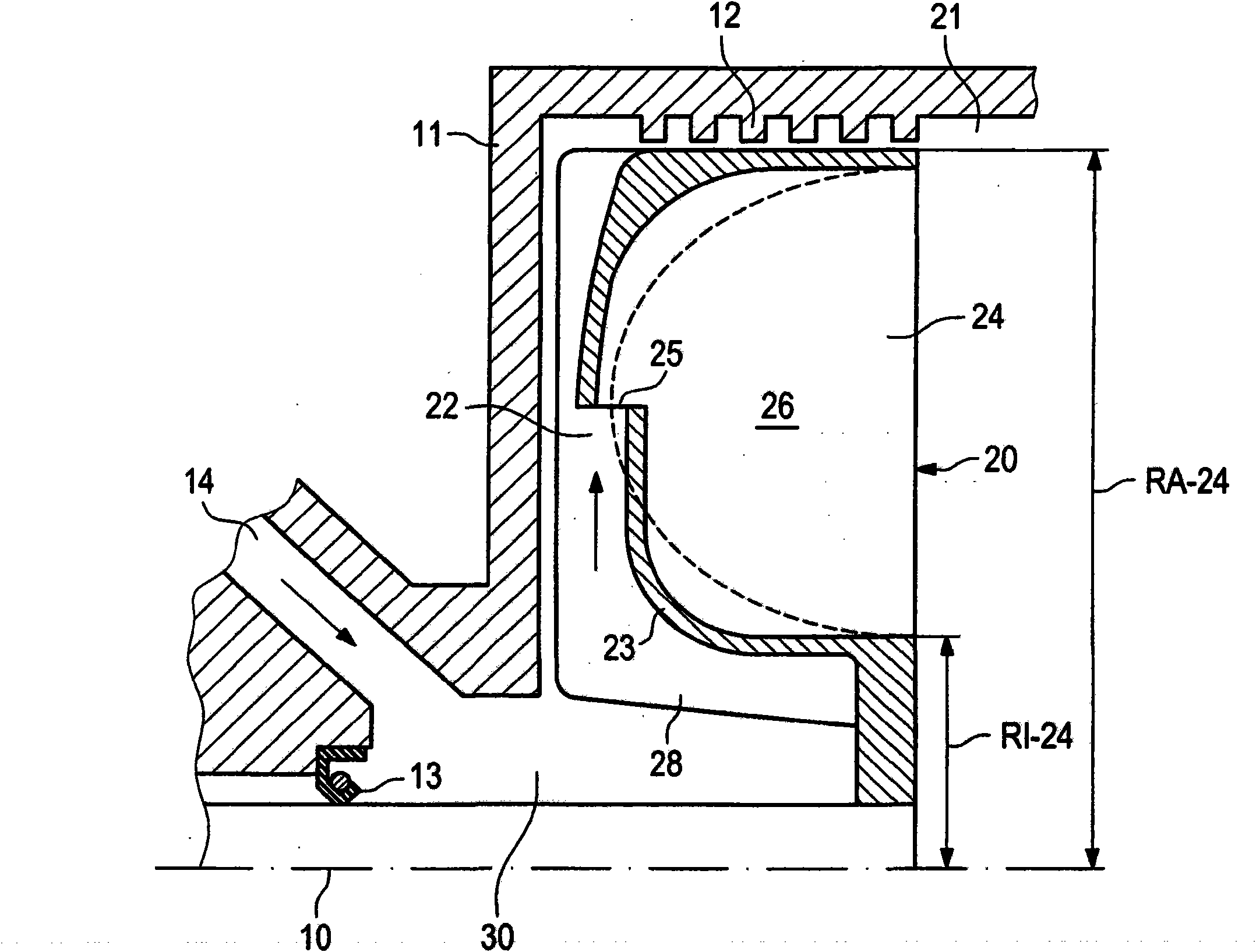
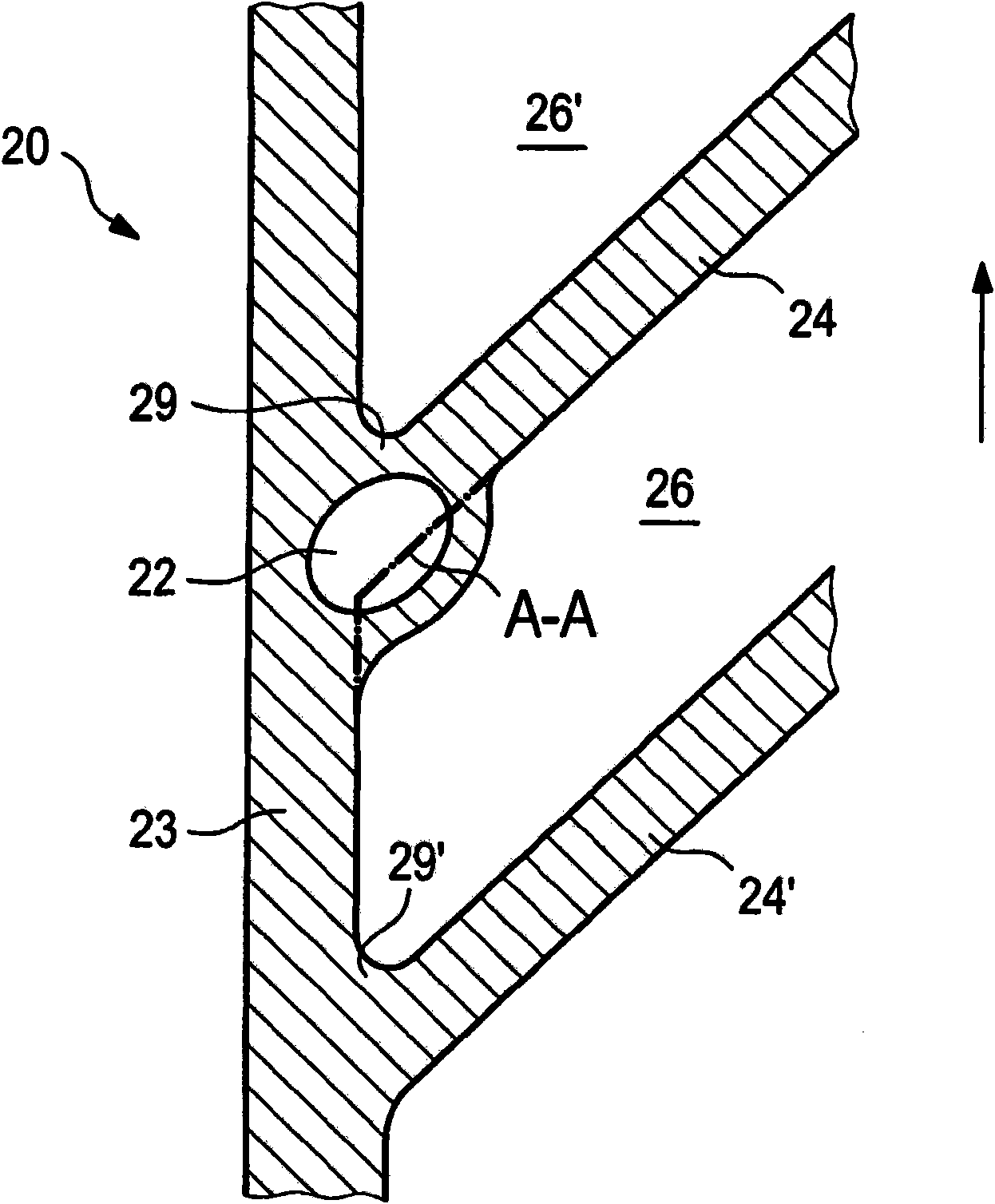
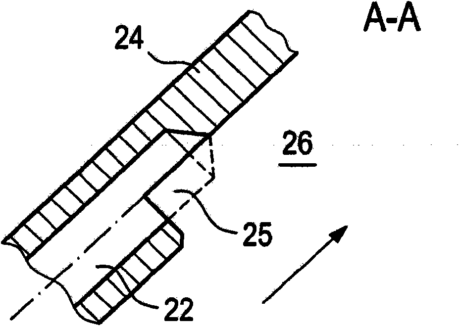
[0026] figure 1A section of the hydrodynamic machine according to the invention is shown along the axis of rotation 10 , having a primary impeller 20 arranged therein. The primary impeller 20 is accommodated here in a machine housing 11 which is provided with a gap seal 12 on the outside relative to the primary impeller 20 . An axial seal 13 is also mounted between the axis of rotation 10 and the housing 11 . The working medium 30 is injected via the supply line 14 into the chamber thus formed (in the direction of the arrow), and as soon as the chamber rotates, the working medium is sucked into the primary impeller 20 via the inlet channel 22 in the torus-shaped working chamber 21 of the machine. In the torus wall 23 . The feed channel 22 is mounted radially from the inside to the outside in the annular wall 23 so that the conveyance of the working medium 30 is supported centrifugally. The inlet channel 22 opens approximately at half the height between the outer diameter R...


PUM


Abstract

A hydrodynamic machine, in particular a hydrodynamic retarder, having a bladed primary wheel (20), which can be rotated via a rotational axle (10) of the hydrodynamic machine, and a bladed secondary wheel which is stationary or can be rotated via the rotational axle of the hydrodynamic machine, wherein the primary wheel and the secondary wheel together form a toroidal working chamber (21) which is filled or can be filled with working medium (30), and the primary wheel has at least one inlet channel (22) for the working medium. The inlet channel extends within the torus wall (23) and / or withina blade (24) of the primary wheel and opens in the region of the centre or radially outside the centre between the outer radius (RA-24) and the inner radius (RI-24) of the blades (24) of the primary wheel (20) at a location in the region of the torus wall in the working chamber.

Description

technical field [0001] The invention relates to a hydrodynamic machine according to the preamble of claim 1 , in particular a hydrodynamic retarder. However, the invention can also be used in hydrodynamic clutches. Background technique [0002] The hydrodynamic gearbox and the hydrodynamic clutch are differentiated by the hydrodynamic torque converter in such a way that they have only two impellers which form a torus-shaped working space between them. In hydrodynamic clutches, the impeller located opposite the pump impeller in hydrodynamic reducers is fixed while the two impellers rotate in the same direction of rotation, or rotates opposite to the pump impeller in so-called counter-rotating reducers . Furthermore, in hydrodynamic clutches, the so-called turbine moves at a rotational speed that is lower than the rotational speed of the pump impeller, since a slip between the two impellers is required for torque transmission from the pump impeller to the turbine. [0003] ...

Claims


Application Information

Patent Timeline
IPC IPC(8): F16D57/04
CPCF16D57/005F16D57/04B60T10/02F16D33/06
Inventor 维尔纳·亚当斯
Owner VOITH PATENT GMBH
Learn More