Hydrodynamic machine, in particular hydrodynamic retarder
A technology of hydraulic machinery and blades, applied in the fields of hydraulic clutches and hydraulic speed reducers
- Summary
- Abstract
- Description
- Claims
- Application Information
AI Technical Summary
Problems solved by technology
Method used
Image
Examples
Embodiment Construction
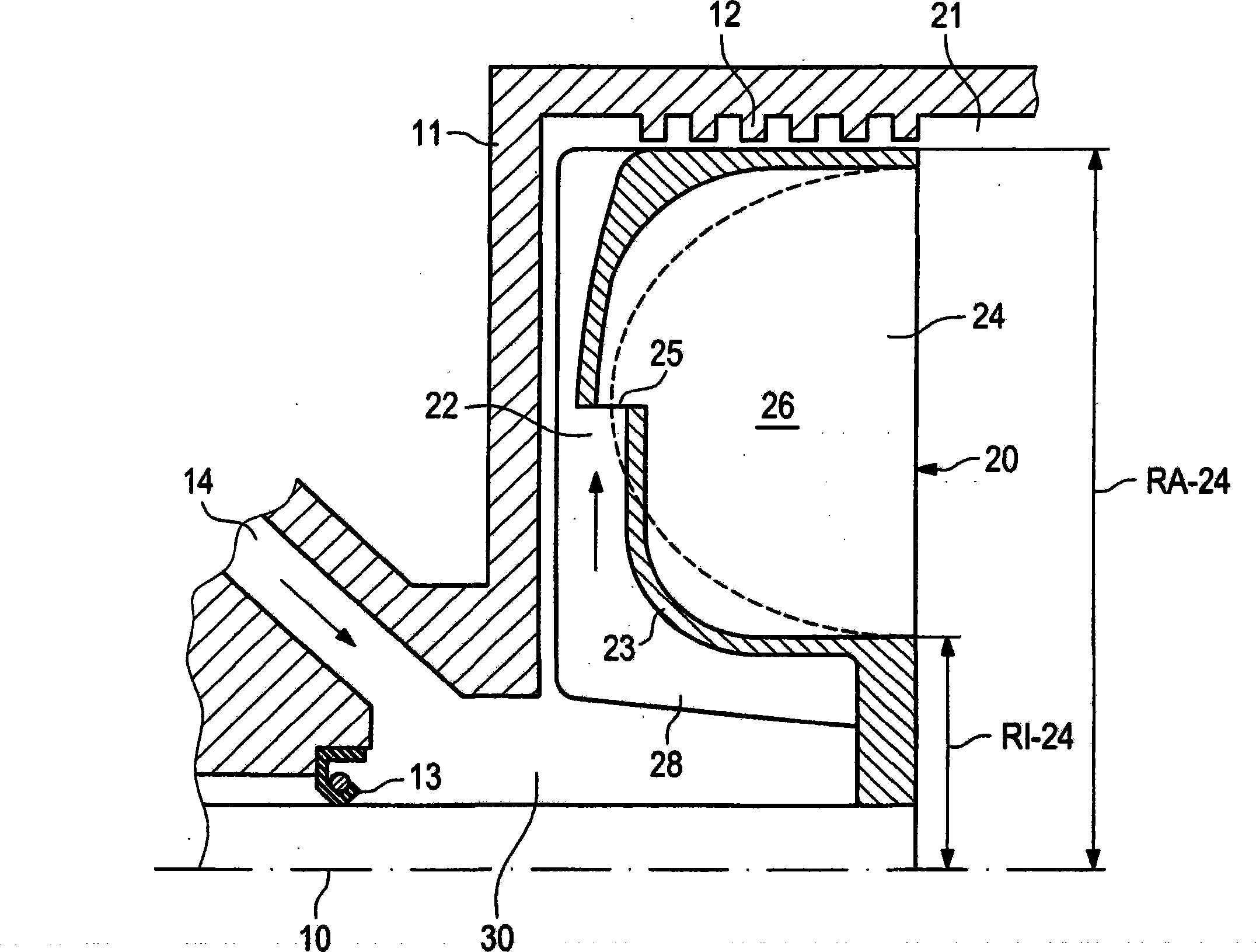
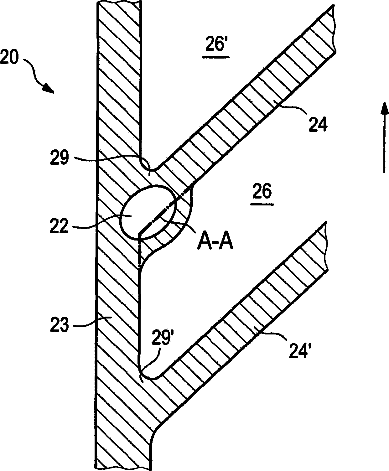
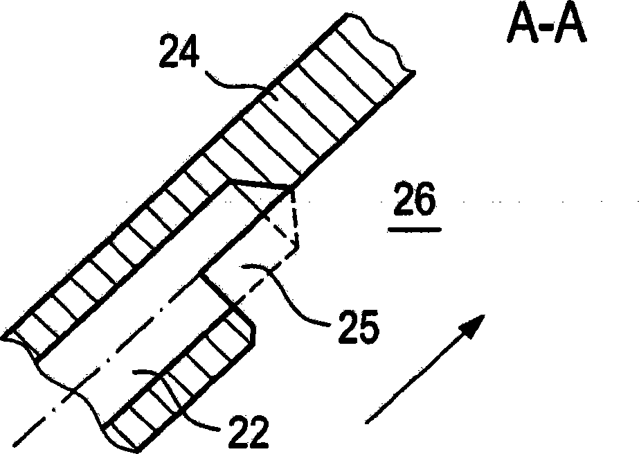
[0027] figure 1 A section of the hydrodynamic machine according to the invention is shown along the axis of rotation 10 , having a primary impeller 20 arranged therein. The primary impeller 20 is accommodated here in a machine housing 11 which is provided with a gap seal 12 on the outside relative to the primary impeller 20 . Between the axis of rotation 10 and the housing 11 an axial seal 13 is also mounted. The working medium 30 is injected via the supply line 14 into the chamber thus formed (in the direction of the arrow), and as soon as the chamber rotates, the working medium is sucked into the primary impeller 20 via the inlet channel 22 in the torus-shaped working chamber 21 of the machine. In the torus wall 23 . The feed channel 22 is mounted radially from the inside to the outside in the annular wall 23 so that the conveyance of the working medium 30 is supported centrifugally. The inlet channel 22 opens approximately at half the height between the outer diameter R...
PUM
 Abstract
Description
Claims
Application Information
 - R&D
- Intellectual Property
- Life Sciences
- Materials
- Tech Scout
- Unparalleled Data Quality
- Higher Quality Content
- 60% Fewer Hallucinations
Browse by: Latest US Patents, China's latest patents, Technical Efficacy Thesaurus, Application Domain, Technology Topic, Popular Technical Reports.
© 2025 PatSnap. All rights reserved.Legal|Privacy policy|Modern Slavery Act Transparency Statement|Sitemap|About US| Contact US: help@patsnap.com


