Door lock actuator

An actuator and door lock technology, applied in the direction of power transmission/actuator feature, electric lock, building lock, etc., can solve the problem of impossible to selectively switch the actuating state, unable to switch the locked state, etc.

Inactive Publication Date: 2010-12-08
U SHIN LTD
View PDF5 Cites 11 Cited by
  • Summary
  • Abstract
  • Description
  • Claims
  • Application Information

AI Technical Summary

Problems solved by technology

[0004] However, in the door lock actuator described in Japanese Unexamined Patent Publication 2003-74242, it is impossible to selectively switch the actuation state
In particular, the door lock actuator can go from the...

Method used


Image

  • Door lock actuator
  • Door lock actuator
  • Door lock actuator

Examples


Embodiment Construction

[0032] A description will be given below of an embodiment according to the present invention with reference to the accompanying drawings.

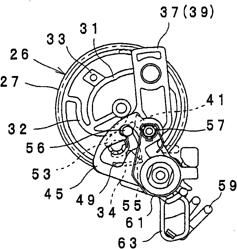
[0033] figure 1 and 2 A door lock actuator according to an embodiment of the invention is shown. The door lock actuator is configured to lock or unlock a door lock device mounted to a door of the vehicle, for example, by the force of the electric motor 24 . In addition, in the present invention, for locking and unlocking, by changing the electrical signals applied to the three connection terminal portions 20A to 20C, it is possible to switch from the unlocked state to the locked state, and from the locked state (unlocked) state to the super-locked state , from the super-locked state to the locked state, and from the locked state (super-locked state) to the unlocked state.

[0034] The door lock actuator is schematically configured such that the motor 24, the worm gear 26 corresponding to the cam member, the rotor 37, the lock button 45,...


PUM


Abstract

The invention discloses a door lock actuator, capable of switching from the super-locking status to the locking status or unlock status, and capable of using simple control to select these status. By rotating to the locking rotary direction, the cam component or worm wheel can rotate the rotor from unlock position to the locking setting position of the lock position to the super-locking setting position through an actuating rotor, the slider is actuated from a connecting status to a non-connecting status at the actuating part of the super-locking setting position, by the rotation in the unlock actuating direction, the slider can be rotated to the locking release position of the actuating rotor from the lock position to the unlock position through the super-locking setting position, and the slider is actuated from a non-connecting status to a connecting status at the actuating part of the super-locking setting position. The cam component is provided with a first operation section, which actuates the moveable touch contacts and stops the cam component at the super lock setting position.

Description

technical field [0001] The present invention relates to a door lock actuator for a vehicle. Background technique [0002] A door lock actuator for a vehicle is configured to rotate a lock lever of a door lock device disposed in a door of the vehicle to a locked position and an unlocked position, for example, by driving a motor. A door lock actuator described in Japanese Unexamined Patent Publication No. 2003-74242 is provided with a button shaft connected to an inner lock button of a vehicle and a rotor connected to a lock lever. The button shaft and the rotor are configured such that they can be switched to a connected state or a connected-disconnected state by the slider. Additionally, the over-locked state is achieved by actuating the slider to the uncoupled state by driving the motor. In this case, the super locked state refers to a state in which the locked state of the door cannot be released even by operating the inner lock knob. [0003] In recent years, counterme...

Claims


Application Information

Patent Timeline
IPC IPC(8): E05B65/20E05B47/06H02K7/10B60R25/01B60R25/20E05B77/28E05B81/16E05B81/42E05B83/36
CPCE05B77/30E05B81/16E05B81/25E05B77/48E05B77/28E05B81/06
Inventor 山形干雄
Owner U SHIN LTD
Why Eureka
Try Eureka