Supercharge Your Innovation With Domain-Expert AI Agents!

Autonomic rotor system for an aircraft

一种飞行器、旋翼的技术,应用在旋翼系统领域,能够解决系统缺少多功能性和可升级性/可扩展性、圆柱形叶片空气动力学叶片外形差距很大等问题,达到提高效率、降低喷管速度的效果

Inactive Publication Date: 2010-12-08
HELISCANDIA
View PDF10 Cites 0 Cited by
  • Summary
  • Abstract
  • Description
  • Claims
  • Application Information

AI Technical Summary

Problems solved by technology

The downside of this system, however, is that these cylindrical blades - which differ greatly from today's aerodynamic blade shapes - have not been proven in practice to be safe in use
[0007] All of these prior art systems are specialized systems that lack the usual versatility and upgradability / expandability

Method used


Image

  • Autonomic rotor system for an aircraft
  • Autonomic rotor system for an aircraft
  • Autonomic rotor system for an aircraft

Examples


Embodiment Construction

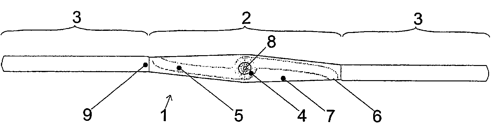
[0070] figure 1 The rotor system seen from above is shown, divided into a drive part 2 and a rotor blade part 3 . The drive part 2 comprises a jet turbine 4 from which a jet flow is conducted via an inner jet duct 5 to a nozzle outlet 6 and thereby directed into a rotary structure 7 . The nozzle outlet 6 is designed such that the jet stream from the nozzle outlet 6 is perpendicular to the longitudinal axis of the rotating structure 7 and acts in the plane of rotation to provide maximum effect. The rotor 1 of the system comprises a rotating structure 7 and rotor blades 3 fixed to the rotating structure 7 by their proximal ends 9 , as opposed to their distal ends, and rotating together with the rotating structure 7 about an axis of rotation 8 .

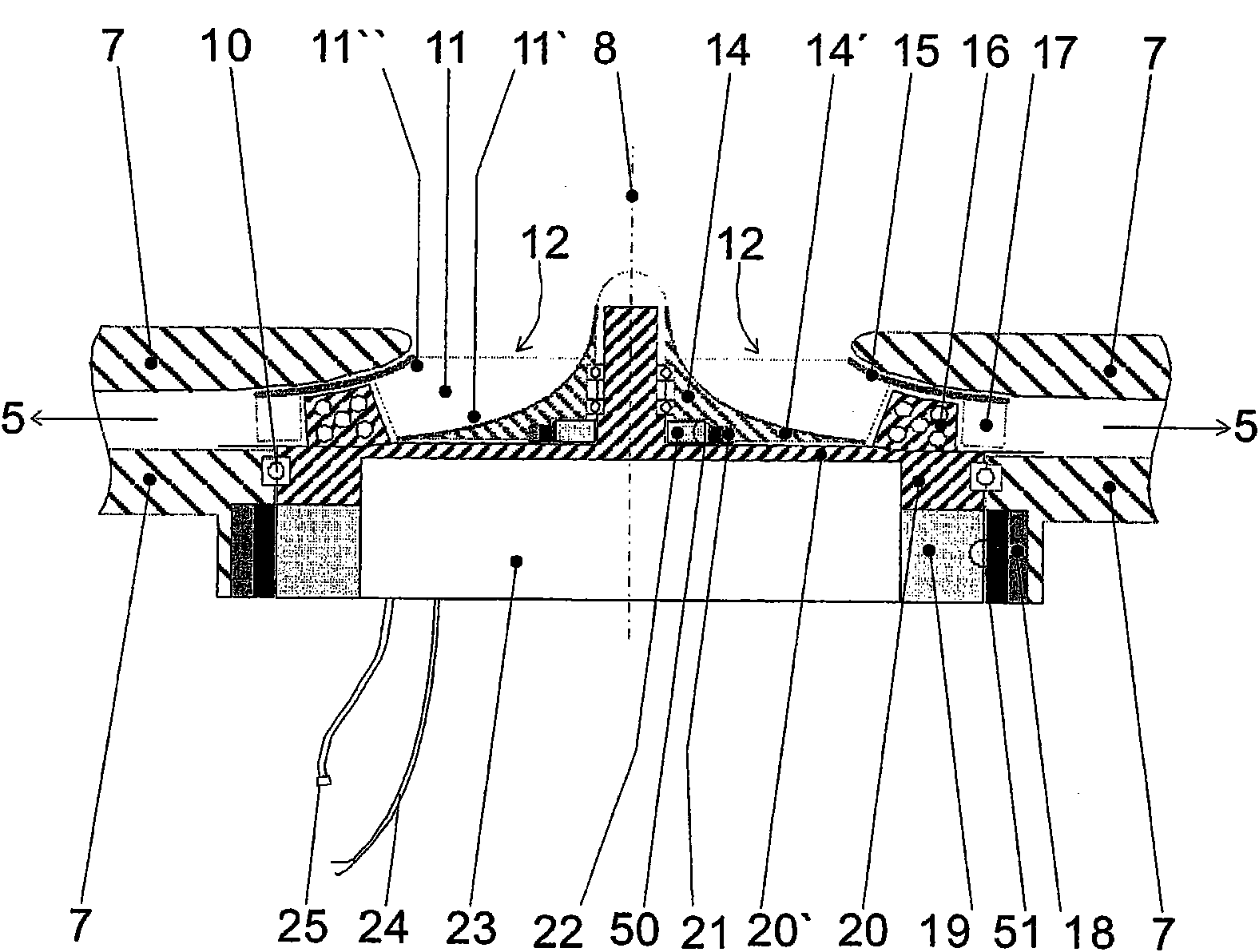
[0071] figure 2 A sectional view of a radial jet turbine 4 is shown. The drive part 2 of the rotor system mainly includes three mechanical structures, which are:

[0072] - a support structure 20 connected to the aircraft;

[007...


PUM


Abstract

A rotor system for an aircraft including a rotor (1) with a drive part (2) mounted rotatable about a rotation axis (8) and supporting the proximal end (9) of at least one rotor blade (3).The rotor system comprises a jet turbine (4) for providing pressurised exhaust gas to a rotary structure(7) having at least one jet nozzle outlet (6) and at least one jet stream duct (5) for transporting the pressurised exhaust gas from the turbine (4) to the jet nozzle outlet (6) to cause rotation of the rotary structure (7) by expelling the pressurised exhaust gas through the nozzle outlet (6). In addition,only the rotary structure(7) and not the rotor blade (3) comprise a jet stream duct (5) and a nozzle outlet (6).

Description

technical field [0001] The invention relates to a rotor system for an aircraft comprising a rotor having a rotating structure mounted for rotation about a rotational axis and supporting the proximal ends of the rotor blades. The rotor system includes a jet turbine for providing pressurized exhaust gas to a rotating structure having at least one nozzle outlet and at least one jet conduit for conveying pressurized exhaust gas from the turbine to the nozzle outlet to cause rotation of the rotating structure by expelling pressurized exhaust gas through the nozzle outlet. Background technique [0002] Aircraft capable of vertical takeoff and landing by means of rotary wings, such as helicopters, are typically constructed in such a configuration that a horizontally rotating main rotor and a vertically rotating tail rotor are coupled to a gearbox and provided by a jet turbine engine. power. A vertical tail rotor is necessary to compensate for the moment exerted by the main rotor ...

Claims


Application Information

Patent Timeline
Patent Type & Authority Applications(China)
IPC IPC(8): B64C27/52B64C27/18
CPCB64C27/18B64C27/52
Inventor G·拉丁
Owner HELISCANDIA
Features
  • R&D
  • Intellectual Property
  • Life Sciences
  • Materials
  • Tech Scout
  • Unparalleled Data Quality
  • Higher Quality Content
  • 60% Fewer Hallucinations
Learn More