
Three-face over-constrained scissor-type lifting mechanism

A lifting mechanism and over-constraint technology, applied in the direction of lifting frame, lifting device, etc., can solve the problems of increasing structural instability, poor structural rigidity, and large force changes of the mechanism, so as to increase the maximum operating height, increase rigidity and The effect of stability and structural stability

Inactive Publication Date: 2010-12-15
TSINGHUA UNIV
View PDF2 Cites 40 Cited by
  • Summary
  • Abstract
  • Description
  • Claims
  • Application Information

AI Technical Summary

Problems solved by technology

Since the two sets of forks are not symmetrical in parallel, when the lifting platform is raised to a high place and receives a lateral force, it is easy to cause the lifting platform to be insufficient in rigidity and shake, and the continuous vibration increases the instability of the structure and even falls over. Therefore, Its structural rigidity is poor
In addition, when the fork lever supporting the platform in the lifting mechanism is fixed at one end and slides at the other end, when the center of gravity of the heavy object carried remains unchanged, it is easy to cause a large change in the force of the mechanism when the lifting platform is raised and lowered, thereby increasing instability. factors, causing work inconvenience and psychological pressure to the top staff, and easily leading to dangerous accidents
On the other hand, if multiple sets of non-parallel fork rods are used to form the lifting mechanism, because the degree of freedom of the mechanism is less than 1 under the current analysis theory of the degree of freedom of the mechanism, it is impossible to synthesize a lifting mechanism that can be put into practical application, which limits the Innovation and Development of Lifting Mechanism

Method used


Image

  • Three-face over-constrained scissor-type lifting mechanism
  • Three-face over-constrained scissor-type lifting mechanism
  • Three-face over-constrained scissor-type lifting mechanism

Examples


Embodiment Construction

[0019] The present invention provides a three-sided over-constrained scissor lift mechanism. The structure, principle and specific implementation of the present invention will be further described below in conjunction with the accompanying drawings.

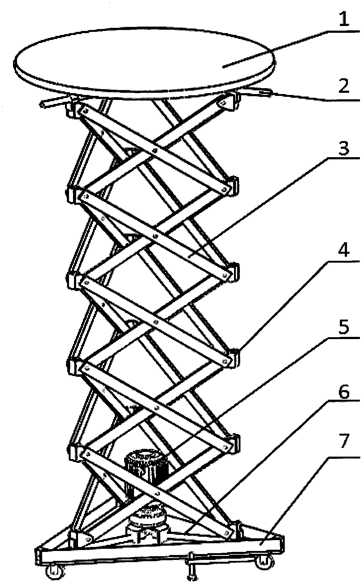
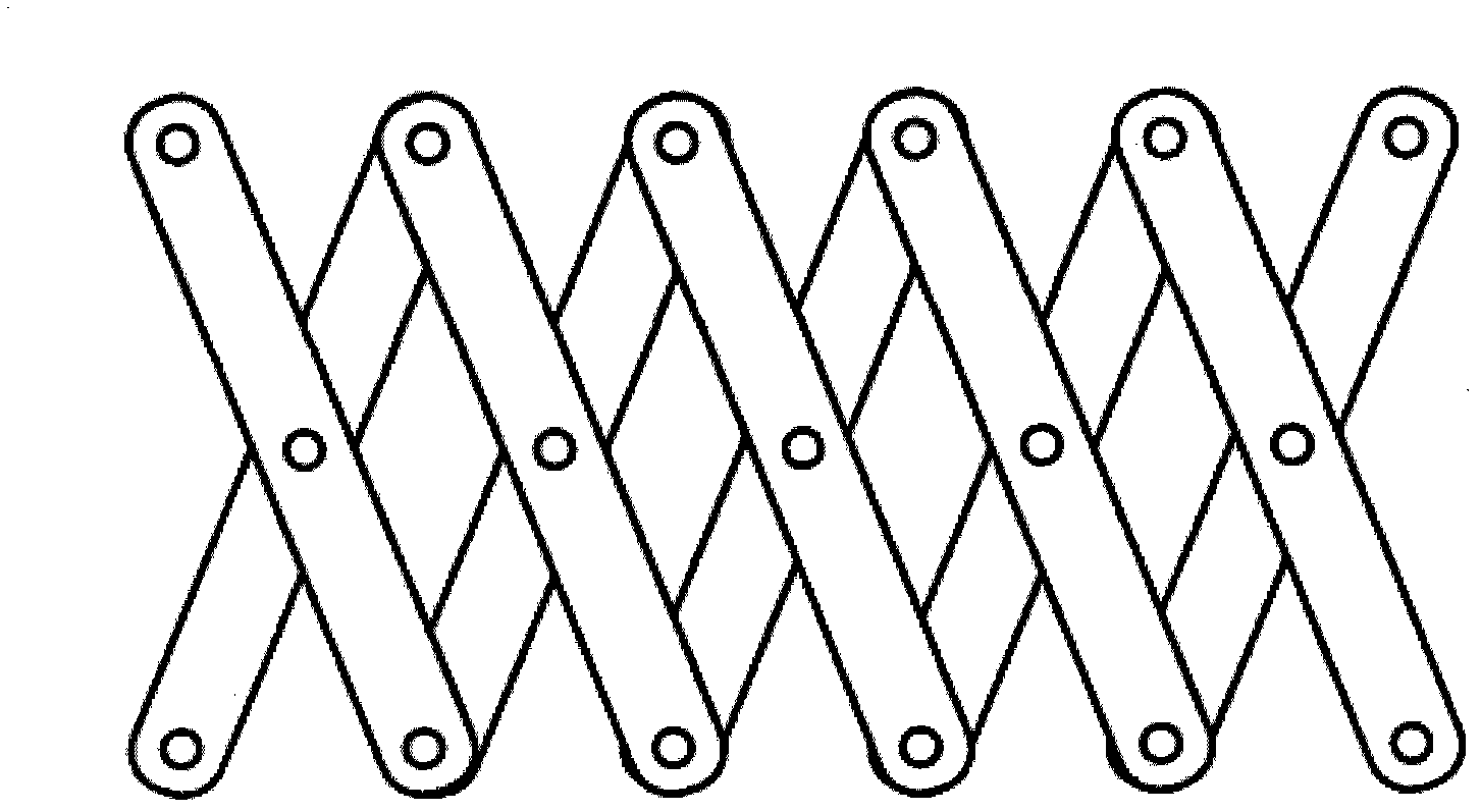
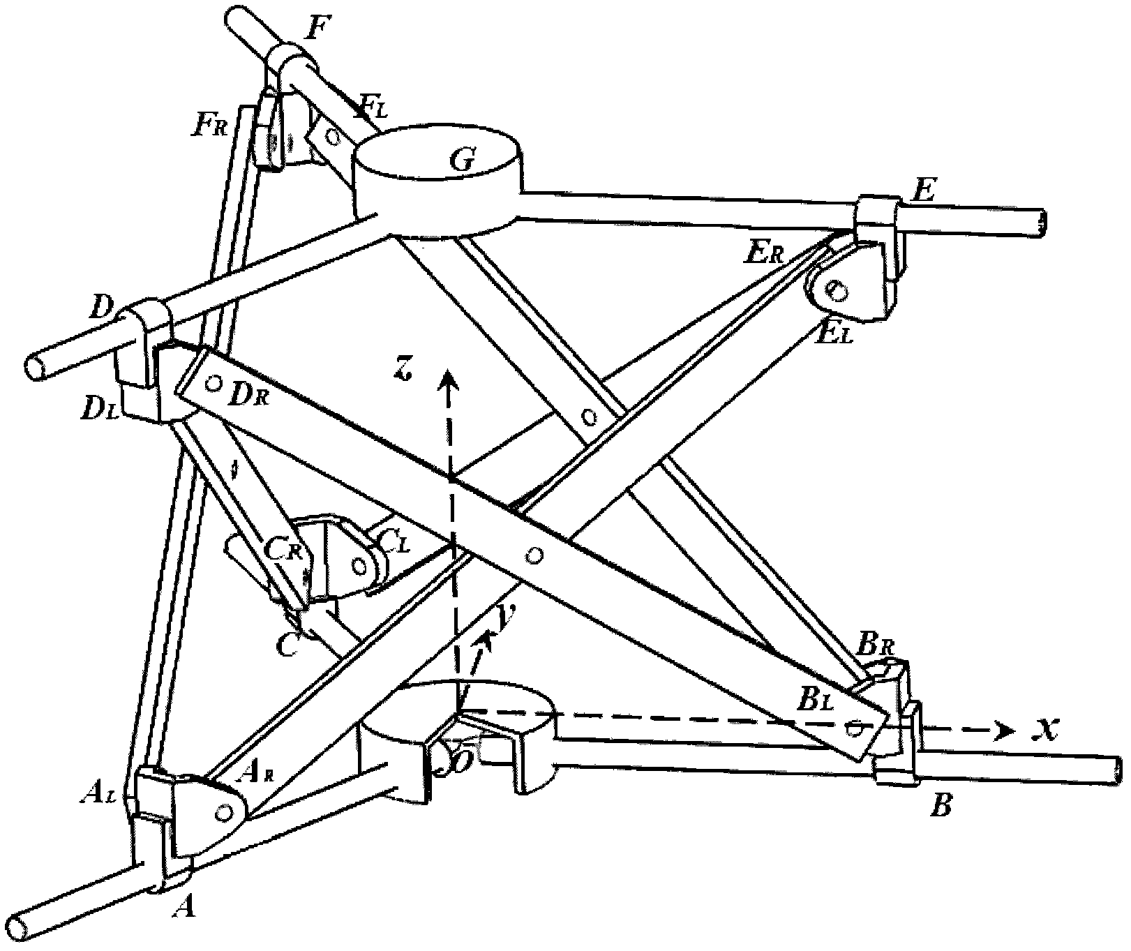
[0020] Such as figure 1 and figure 2 As shown, the structure of the lifting mechanism includes a supporting platform 1 , an upper guide rail 2 , a scissor truss 3 , a connecting piece 4 , a lower guide rail 6 , and a base 7 . The scissor truss 3 is an expandable mechanism composed of a plurality of scissor units, a pair of connecting rods of each scissor unit is connected by a rotating pair, and each pair of connecting rods can only rotate around the The axis of the plane where the connecting rod is located is relatively rotated, and at the same time, both ends of the connecting rod are connected to other scissor-type units through a rotating pair parallel to the axis of the middle rotating pair; the three-sided over-constraine...


PUM


Abstract

The invention relates to the field of lifting equipments, particularly to a three-face over-constrained scissor-type lifting mechanism. The mechanism comprises three groups of scissor-type trusses; the plane that each truss is located is vertical to the ground; an included angle between every two trusses is 60 degrees, therefore, the trusses are arranged in a regular triangle; the scissor-type trusses are connected via a plurality of connectors and connected with the connectors via revolute pairs; a lower guide rail is fixedly connected with a base and respectively connected with three connectors at the bottom via prismatic pairs; an upper guide rail is fixedly connected with a bearing platform and connected with three connectors at the top via prismatic pairs; and when the scissor-type trusses are unfolded, the bearing platform is vertically hoisted. The mechanism has the advantages of high strength, large structure rigidity and high motion stability, can be applied to works of overhead installation, maintenance, transportation, and the like, and can bear larger load and satisfy higher work height requirements.

Description

technical field [0001] The invention relates to the field of lifting equipment, in particular to a three-sided over-constrained scissor-type lifting mechanism. Background technique [0002] A lifting platform is a lifting machine that transports people or objects vertically. In addition to transporting goods at different heights, lifting platforms are widely used in high-altitude installation, maintenance and other operations. Its free lifting characteristics have been widely used in municipal maintenance, cargo transportation in docks and logistics centers, and building decoration. It has light weight, Self-propelled, electric start, self-supporting legs, simple operation, large working area and other advantages. [0003] According to the different lifting mechanisms used, lifting platforms can be divided into scissor lifts, telescopic lifts, telescopic lifts, telescopic arm lifts, folding arm lifts, etc.; according to different moving methods, they can be divided into fix...

Claims


Application Information

Patent Timeline
Patent Type & Authority Applications(China)
IPC IPC(8): B66F7/06B66F7/28
Inventor 赵景山王建宜褚福磊
Owner TSINGHUA UNIV
Learn More