Cable take-up device and use method thereof

A technology of winding device and cable reel, which is applied in the direction of transportation and packaging, delivery of filamentous materials, thin material processing, etc., can solve the problems of troublesome production operations, slipping of reels, time-consuming and labor-intensive, etc., to reduce working costs, The effect of reducing energy loss and reducing frictional resistance

Inactive Publication Date: 2019-01-25
义乌市建信金属材料有限公司
View PDF0 Cites 2 Cited by
  • Summary
  • Abstract
  • Description
  • Claims
  • Application Information

AI Technical Summary

Problems solved by technology

[0002] Cables are divided into power cables, control cables, compensation cables, shielded cables, high-temperature cables, computer cables, signal cables, coaxial cables, fire-resistant cables, marine cables, mining cables, aluminum alloy cables, etc. Composed of strands or multi-strand wires and insulating layers, it is used to connect circuits, electrical appliances, etc. It is one of the important components of electric power construction. In order to facilitate cable transportation, it must be rolled up after production to save storage space. The current cables The structure of the winding machine is relatively simple, the function is less, and the use effect is not good, which brings a lot of troubles to the production operation, and when the cable is rolled, the steps of replacing the reel are very cumbersome. The disk shaft slips off, which affects the normal operation, and manual adjustment is required, which is time-consuming and laborious

Method used


Image

  • Cable take-up device and use method thereof
  • Cable take-up device and use method thereof
  • Cable take-up device and use method thereof

Examples


Embodiment Construction

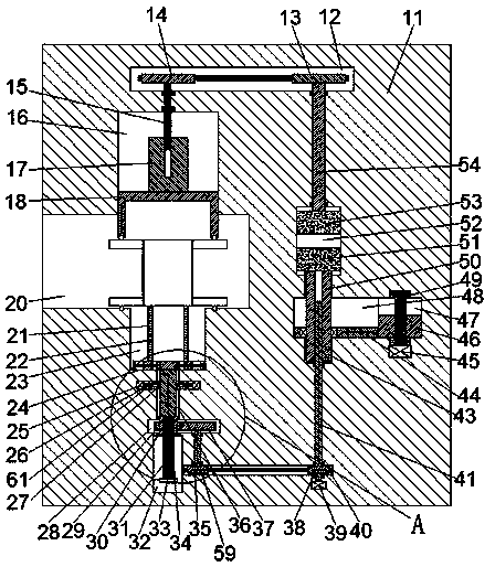
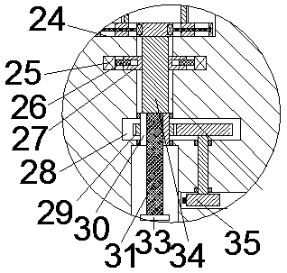
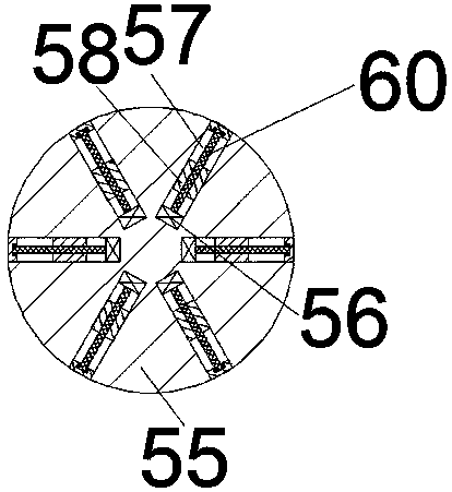
[0016] Combine below Figure 1-3 The present invention is described in detail, and for the convenience of description, the orientations mentioned below are now stipulated as follows: figure 1 The up, down, left, right, front and back directions of the projection relationship itself are the same.

[0017] refer to Figure 1-3A cable winding device according to an embodiment of the present invention includes a base body 11, a first cavity 40 is arranged in the base body 11, a first pulley 38 is installed in the first cavity 40, and a first pulley 38 is installed in the first cavity 40. A drive motor 39 connected to the first pulley 38 through a rotating shaft is installed in the lower end wall of a cavity 40, and a spline shaft 41 extending up and down is rotatably installed in the upper end wall of the first cavity 40, so The lower end of the spline shaft 41 extends into the first cavity 40 and is fixedly connected with the first pulley 38. A second cavity 48 is arranged in t...


PUM


Abstract

The invention discloses a cable take-up device which comprises a substrate. A first cavity is formed in the substrate, a first belt wheel is arranged in the first cavity, a driving motor is mounted inthe lower end wall of the first cavity and in power connection with the first belt wheel through the first belt wheel, a spline shaft vertically extends and is rotatably mounted on the upper end wallof the first cavity, the lower end of the spline shaft extends the first cavity and fixedly connected with the first belt wheel, a second cavity is formed in the upper end wall of the first cavity, aspline sleeve is arranged in the upper end wall and the lower end wall of the second cavity in a sliding fit manner and mounted on the spline shaft and can vertically extend, and a moving rod is slidably matched with the second cavity and mounted on a sliding groove in the spline sleeve in a sliding fit manner.

Description

technical field [0001] The invention relates to the technical field of cable storage and transportation, in particular to a cable winding device and a method for using the same. Background technique [0002] Cables are divided into power cables, control cables, compensation cables, shielded cables, high-temperature cables, computer cables, signal cables, coaxial cables, fire-resistant cables, marine cables, mining cables, aluminum alloy cables, etc. Composed of strands or multi-strand wires and insulating layers, it is used to connect circuits, electrical appliances, etc. It is one of the important components of electric power construction. In order to facilitate cable transportation, it must be rolled up after production to save storage space. The current cables The structure of the winding machine is relatively simple, the function is less, and the use effect is not good, which brings a lot of troubles to the production operation, and when the cable is rolled, the steps of...

Claims


Application Information

Patent Timeline
Patent Type & Authority Applications(China)
IPC IPC(8): B65H54/54B65H54/44
CPCB65H54/54B65H54/44B65H2701/34
Inventor 卜美燕
Owner 义乌市建信金属材料有限公司
Why Eureka
Try Eureka