Multi-channel type planet traction transmission bearing type speed reducer

A technology of traction transmission and multi-channel, which is applied in transmission devices, friction transmission devices, belts/chains/gears, etc., which can solve the problem of reducing the torsional offset of the rolling element shaft system, the large axial dimension of the overall structure, and the inability to Effectively withstand problems such as axial force, to achieve the effect of increasing installation flexibility, eliminating jamming, and improving smooth operation

Pending Publication Date: 2019-02-22
CHONGQING UNIV
View PDF7 Cites 1 Cited by
  • Summary
  • Abstract
  • Description
  • Claims
  • Application Information

AI Technical Summary

Problems solved by technology

[0004] Patent CN205639286U discloses a planetary traction transmission reduction bearing, the smooth surface fit is used between the rolling elements and the inner and outer rings, this structure cannot bear the axial load, in order to ensure that it can withstand a certain axial load, it is necessary to add an additional shaft Directional positioning device, resulting in complex deceleration bearing structure, the overall structure is larger in the axial direction, and the structure will affect the normal operation of the transmission when bearing the axial force, and cause a great drop in efficiency; during the working process of this structure, the output The resistance moment or bending moment on the shaft will act on the rolling element, resulting in a moment difference at both ends of the rolling element. This moment difference will cause the rolling element to twist and deform in the direction of its a

Method used


Image

  • Multi-channel type planet traction transmission bearing type speed reducer
  • Multi-channel type planet traction transmission bearing type speed reducer
  • Multi-channel type planet traction transmission bearing type speed reducer

Examples


Embodiment Construction

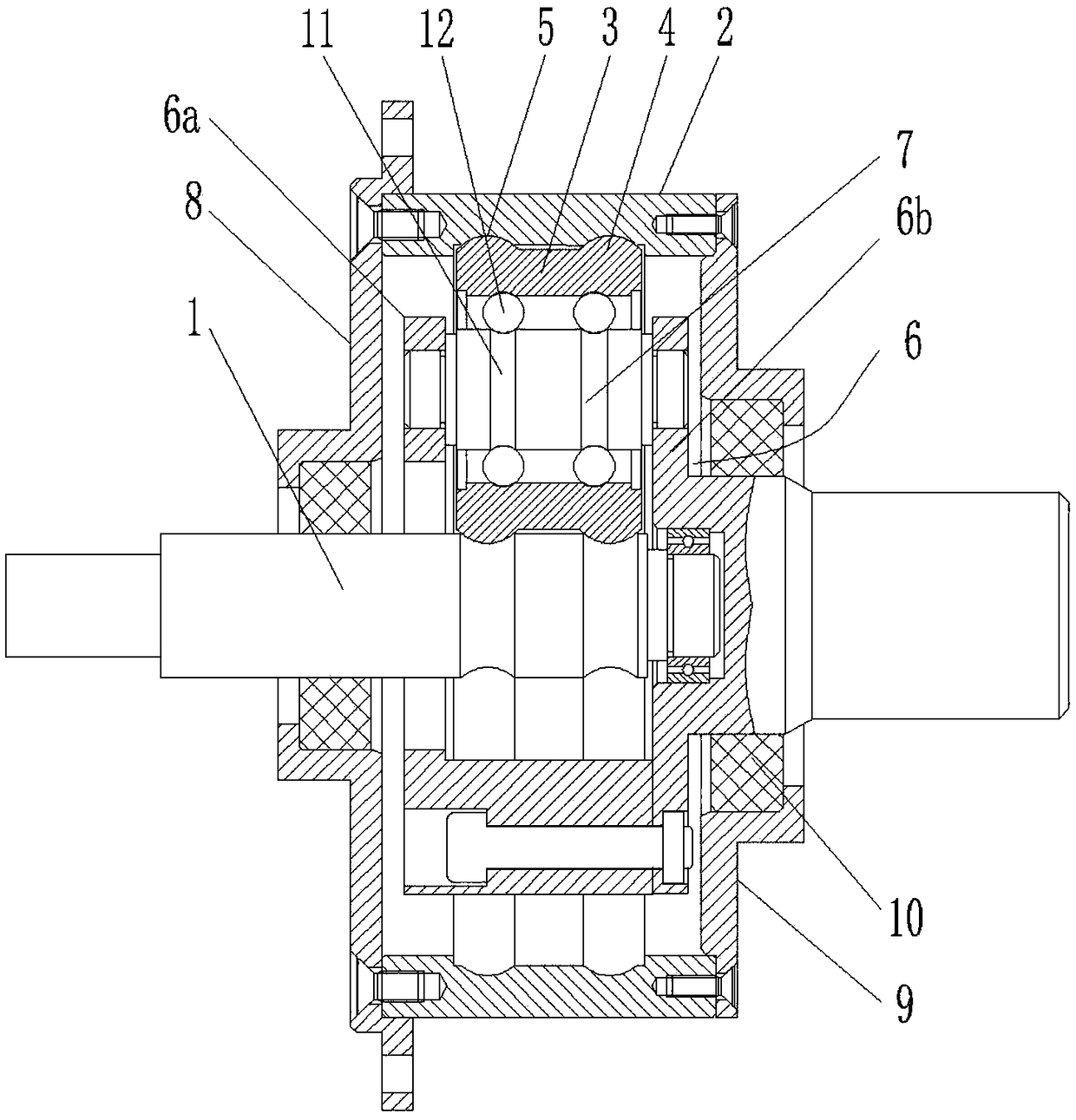
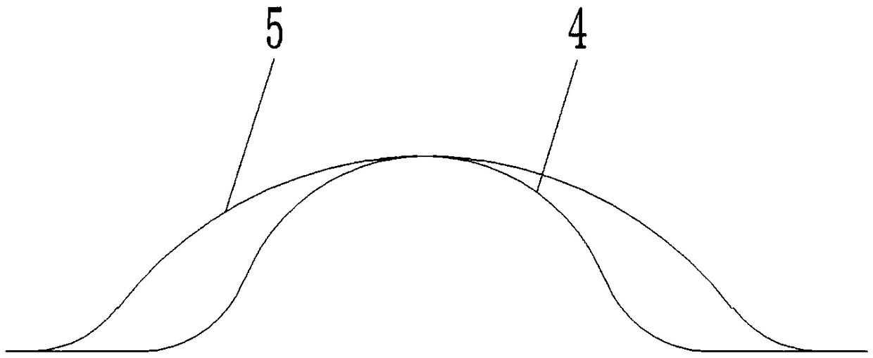
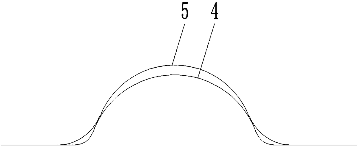
[0028] figure 1 It is a structural schematic diagram of the present invention; figure 2 It is a structural schematic diagram of the first cooperation mode between the annular protrusion and the annular channel; image 3 It is a structural schematic diagram of the second cooperation mode between the annular protrusion and the annular channel; Figure 4 It is a structural schematic diagram of the third cooperation mode between the annular protrusion and the annular channel;

[0029]As shown in the figure: the multi-channel planetary traction transmission bearing type reducer of this embodiment includes a planetary traction transmission gear train formed by transmission inner shaft 1, outer ring 2, planetary rolling element 3 and planet carrier 6. Between the outer circle of the planetary rolling body 3 and the inner circle of the outer ring 2, and between the outer circle of the planetary rolling body 3 and the outer circle of the transmission inner shaft 1, a matching pair i...


PUM


Abstract

The invention discloses a multi-channel type planet traction transmission bearing type speed reducer. The multi-channel type planet traction transmission bearing type speed reducer comprises a planettraction transmission wheel system formed by a transmission inner shaft, an outer ring, a planet rolling body and a planet carrier jointly. Cooperation pairs are formed between the outer circle of theplanet rolling body and the inner circle of the outer ring and between the outer circle of the planet rolling body and the outer circle of the transmission inner shaft through annular protrusions andannular channels, and the planet rolling body cooperates with the transmission inner shaft and the outer ring in a friction transmission manner. By means of the mutual structural constraint of the annular protrusions and the annular channels, when torque is transmitted between the transmission inner shaft and the planet rolling body, relative displacement of the planet rolling body and the transmission inner shaft in the axial direction and the radial direction of the outer ring can be effectively limited, the functions of a bearing and reduction transmission are achieved, and the speed reducer is high in supporting rigidity, stable in transmission and compact in structure.

Description

technical field [0001] The invention belongs to the technical field of planetary reducers, in particular to a multi-channel planetary traction transmission bearing type reducer. Background technique [0002] A planetary reducer is a device that uses a planetary reduction mechanism to achieve deceleration. Due to its small size and large transmission ratio, the planetary reducer is usually used in devices with limited installation space for the reducer, such as hub motors, etc. The existing planetary reducer The planetary gear reducer usually adopts a planetary gear reduction mechanism, that is, the planetary gear is used as a planetary rolling body, and it transmits power through gear meshing with the inner and outer rings at the same time. However, the existing planetary reducer uses planetary gear meshing for transmission. , because the pitch error of the planetary gear will cause periodic impact, resulting in strong transmission fluctuation and high noise. At the same tim...

Claims


Application Information

Patent Timeline
IPC IPC(8): F16H13/08
CPCF16H13/08
Inventor 舒红宇
Owner CHONGQING UNIV
Why Eureka
Try Eureka