Double-motor coupling planetary traction transmission shaft bearing type deceleration electric hub

A traction drive, electric wheel hub technology, applied in power plant, motion deposition, vehicle components, etc., can solve the problems of increased vibration and noise, small wheel hub torque, increased number of bearings, etc., to improve transmission torque and power, support operation Smooth, increased contact area effect

Inactive Publication Date: 2019-03-29
CHONGQING UNIV
View PDF6 Cites 6 Cited by
  • Summary
  • Abstract
  • Description
  • Claims
  • Application Information

AI Technical Summary

Problems solved by technology

[0002] The existing electric wheel hub structure is mainly composed of a central shaft, a housing mounted on the central shaft through bearings, a motor located in the housing, a planetary reduction mechanism, a clutch and other components. Rotation usually requires independent bearings for support. The motor rotor, the planet carrier of the planetary gear reducer, and the hub body are all supported and rotated by independent bearings. This structure greatly increases the number of bearings in the hub motor, resulting in a complex overall structure of the hub motor , which increases the production cost and the difficulty of assembly, and the components such as motor, reducer and bearing need to be arranged in sequence in the axial direction, which greatly increases the axial size of the hub structure, resulting in limited layout space for the hub position. Limitation of layout space Usually only one stage of deceleration mechanism is installed. The power of the motor is output to the motor side through the primary deceleration mechanism and drives the hub to rotate. The transmission ratio is low, and it is difficult to use a high-speed motor as the power of the hub motor, resulting in torque on the hub Small size, low speed, high noise, etc.
[0003] CN106655613A discloses a double-stage deceleration bearing type wheel hub motor. The motor is powered by a two-stage planetary traction deceleration bearing. The planetary rolling elements in the planetary traction deceleration bearing and the inner and outer rings adopt smooth cooperation. This structure It cannot bear the axial load. In order to ensure that it can withstand a certain axial load, an additional axial positioning device needs to be added, resulting in a complex structure of the reduction bearing, and the overall structure has a large size in the axial direction. The efficiency is greatly reduced; during the working process of this structure, the resistance moment or bending moment on the output shaft will act on the planetary rolling element, resulting in a torque difference at both ends of the planetary rolling element, which will cause the planetary rolling element to twist in its Oblique deformation occurs in the direction of the axis, which will lead to increased vibration and noise, reduced efficiency, jamming during operation, resulting in unsmooth operation, and even jamming;

Method used


Image

  • Double-motor coupling planetary traction transmission shaft bearing type deceleration electric hub
  • Double-motor coupling planetary traction transmission shaft bearing type deceleration electric hub
  • Double-motor coupling planetary traction transmission shaft bearing type deceleration electric hub

Examples


Embodiment Construction

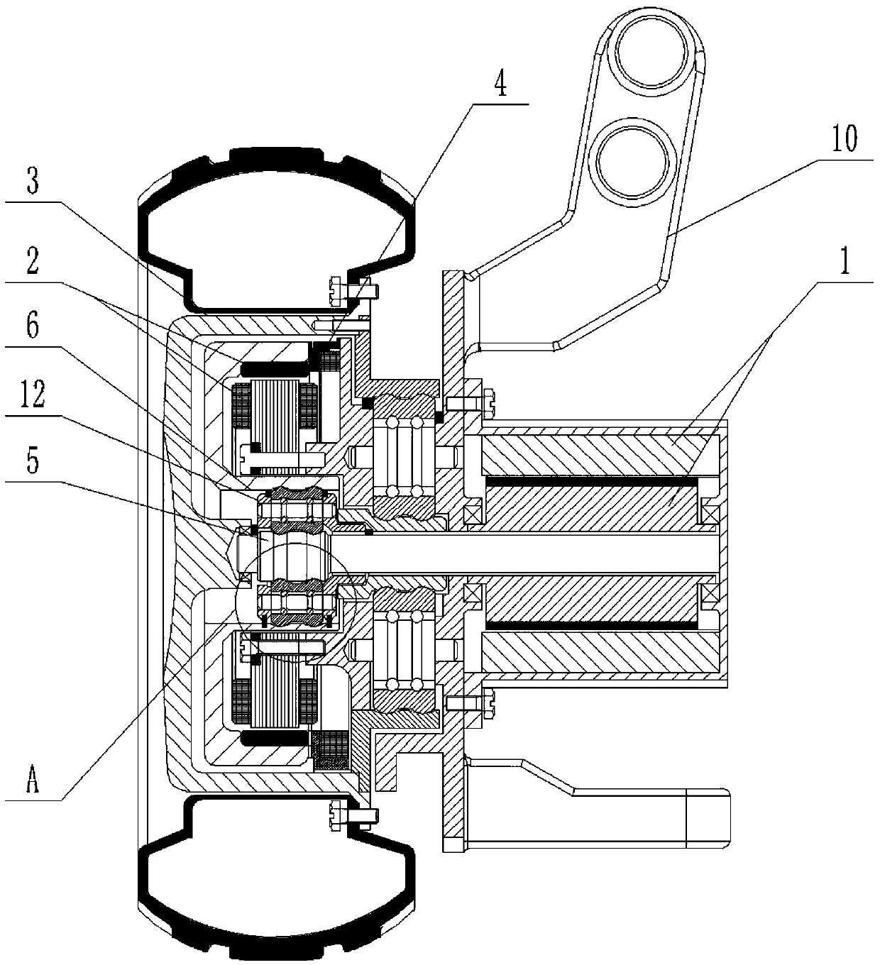
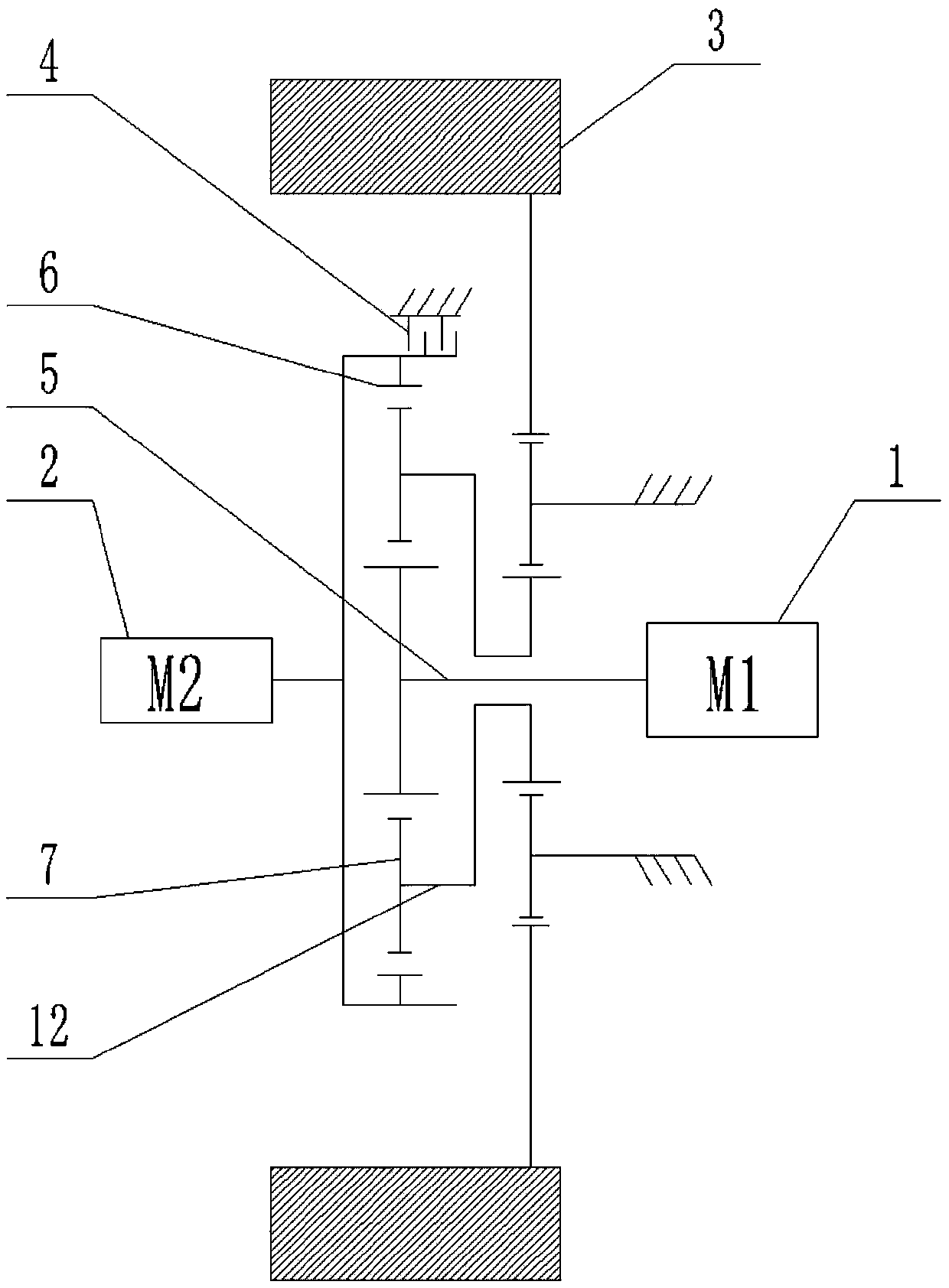
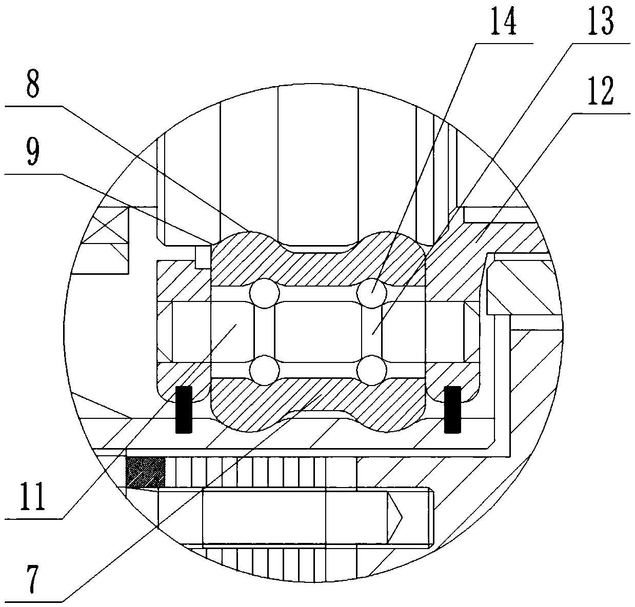
[0031] figure 1 It is a structural schematic diagram of the present invention; figure 2 It is a schematic structural diagram of the principle of the present invention; image 3 for figure 1 Schematic diagram of the enlarged structure at point A; Figure 4 It is a structural schematic diagram of the first cooperation mode between the annular protrusion and the annular channel; Figure 5 It is a structural schematic diagram of the second cooperation mode between the annular protrusion and the annular channel; Image 6 It is a structural schematic diagram of the third cooperation mode between the annular protrusion and the annular channel;

[0032]As shown in the figure: the dual-motor coupling planetary traction transmission bearing type deceleration electric hub of this embodiment includes a hub 3, a planetary traction transmission bearing type reducer, and No. 1 motor 1 and No. 2 motor 2; the accommodating cavity is provided with Planetary traction transmission bearing t...


PUM


Abstract

The invention discloses a double-motor coupling planetary traction transmission shaft bearing type deceleration electric hub, which comprises a hub, a planetary traction transmission shaft bearing type speed reducer arranged in a hub cavity, a first motor and a second motor. Any sequence combination of a sun gear, a planet carrier and an outer ring in the planetary traction transmission shaft bearing type speed reducer respectively corresponds to a power input end, a power output end and an intermediate transmission part in the planetary traction transmission shaft bearing type speed reducer,the first motor is used for driving the power input end to provide power and driving the hub to rotate through the power output end, and the second motor is used for driving the intermediate transmission part for speed coupling. According to the planetary traction transmission shaft bearing type speed reducer, the cooperation of the two motors is realized through the planetary traction transmission shaft bearing type speed reducer, so that each motor can always work in a high-efficiency working range, the working efficiency of the hub is improved, and the purposes of saving energy and prolonging endurance mileage are achieved.

Description

technical field [0001] The invention belongs to the technical field of automobiles, and in particular relates to a double-motor coupling planetary traction transmission bearing type deceleration electric wheel hub. Background technique [0002] The existing electric wheel hub structure is mainly composed of a central shaft, a housing mounted on the central shaft through bearings, a motor located in the housing, a planetary reduction mechanism, a clutch and other components. Rotation usually requires independent bearings for support. The motor rotor, the planet carrier of the planetary gear reducer, and the hub body are all supported and rotated by independent bearings. This structure greatly increases the number of bearings in the hub motor, resulting in a complex overall structure of the hub motor , which increases the production cost and the difficulty of assembly, and the components such as motor, reducer and bearing need to be arranged in sequence in the axial direction,...

Claims


Application Information

Patent Timeline
Patent Type & Authority Applications(China)
IPC IPC(8): B60K7/00B60K17/04
CPCB60K7/0007B60K17/046B60K2007/003B60K2007/0061
Inventor 舒红宇
Owner CHONGQING UNIV
Why Eureka
Try Eureka