
Novel hydraulic driving system for scraper conveyer

A scraper conveyor and drive system technology, applied in conveyors, transportation and packaging, etc., can solve the problems of disassembly, maintenance, wear, and seal failure, so as to improve system reliability and economy, and reduce equipment investment. , the effect of reducing the height of the device

Inactive Publication Date: 2012-07-11
CHINA COAL ZHANGJIAKOU COAL MINING MACHINERY
View PDF5 Cites 12 Cited by
  • Summary
  • Abstract
  • Description
  • Claims
  • Application Information

AI Technical Summary

Problems solved by technology

At present, the scraper conveyor usually adopts two-speed motor drive, single-speed motor plus hydraulic coupling drive and variable frequency motor drive, etc., each has advantages and disadvantages in application, and its common disadvantage is that the motor and transmission device are connected with the sprocket, and the tail is suspended. The connection strength and neutrality requirements are high, and problems such as vibration, noise, wear, heat generation, and seal failure are prone to occur; the unloading height of the scraper conveyor is difficult to reduce, making it difficult to realize the mining of thin coal seams, and the drive motor needs to be laid over a long distance Large-capacity cables lead to bulky nose and tail, making it difficult to disassemble and maintain in the narrow space underground

Method used


Image

  • Novel hydraulic driving system for scraper conveyer
  • Novel hydraulic driving system for scraper conveyer
  • Novel hydraulic driving system for scraper conveyer

Examples


Embodiment Construction

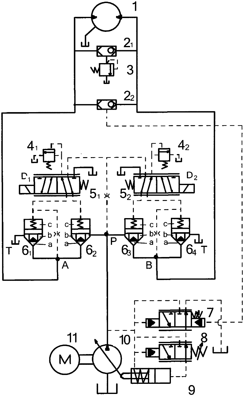
[0010] Depend on figure 1 , 2 As shown, the new hydraulic drive system of the scraper conveyor includes an oil tank and an electric control system, which is characterized by: a hydraulic motor 1, a shuttle valve, a safety valve 3, an overflow valve, a proportional reversing valve, a flow type cartridge valve, Load sensing valve 7, pressure cut-off valve 8, variable piston 9, variable pump 10, and motor 11; the output shaft of hydraulic motor 1 is connected to the sprocket shaft of the scraper conveyor, and the two ends of hydraulic motor 1 are connected in parallel with the first shuttle valve 2 1 and the second shuttle valve 2 2 , the first shuttle valve 2 1 The outlet is connected in series with safety valve 3 and the second shuttle valve 2 2 The outlet of the load sensing valve 7 is connected in series to the right chamber of the control end, the oil outlet of the load sensing valve 7 is connected with the oil outlet of the pressure cut-off valve 8, and the right end of ...


PUM


Abstract

The invention relates to a hydraulic driving system, in particular to a novel hydraulic driving system for a scraper conveyer, which aims to the overcome the defect that as the existing scraper conveyer is commonly driven by a two-speed motor, a single speed motor plus a hydraulic coupling, a variable-frequency motor and the like, when a motor, a transmission device and a chain wheel are connected with one another, the tail part is suspended, resulting in easy generation of vibration, abrasion, invalid sealing and the like. The novel hydraulic driving system consists of a hydraulic motor, a shuttle valve, a safety valve, an overflow valve, a proportional reversing valve, a flow type cartridge valve, a load sensing valve, a pressure cutoff valve, a variable piston, a variable pump and a motor. The novel hydraulic driving system has the beneficial effects that the soft start of the scraper conveyer is realized by applying a load sensing system, a variable pump-quantitative motor type volume speed control circuit and a flow type proportional cartridge valve control element; the rotating speed of the hydraulic motor can be controllable, can also be subjected to stepless speed regulation within a certain scope and is not affected by load change and motor rotating speed fluctuation; and the working requirements on high pressure and large flow rate of the system are satisfied, and equipment operation and braking are ensured to be stable and reliable.

Description

technical field [0001] The invention relates to a hydraulic drive system, in particular to a novel hydraulic drive system of a scraper conveyor. Background technique [0002] The scraper conveyor is the key equipment for underground coal transportation in coal mines. As the driving device of the scraper conveyor is the power system of the scraper conveyor, the rationality and reliability of the design are very important. At present, the scraper conveyor usually adopts two-speed motor drive, single-speed motor plus hydraulic coupling drive and variable frequency motor drive, etc., each has advantages and disadvantages in application, and its common disadvantage is that the motor and transmission device are connected with the sprocket, and the tail is suspended. The connection strength and neutrality requirements are high, and problems such as vibration, noise, wear, heat generation, and seal failure are prone to occur; the unloading height of the scraper conveyor is difficult...

Claims


Application Information

Patent Timeline
Patent Type & Authority Applications(China)
IPC IPC(8): B65G23/00
CPCY02P70/10
Inventor 聂文科王彪冀贵李玉春尤晓明王会来裴国霞黄政委
Owner CHINA COAL ZHANGJIAKOU COAL MINING MACHINERY
Learn More