Mechanical mechanism for converting reciprocating motion power into rotary power

A mechanical mechanism and reciprocating motion technology, applied in the direction of mechanical equipment, transmission devices, belts/chains/gears, etc., can solve the problems of non-adjustable ratio of torque and speed, low mechanical efficiency, vibration of mechanical equipment, etc., to achieve convenience and stepless Speed ​​regulation or stepped speed regulation, low production cost and high mechanical efficiency

Inactive Publication Date: 2010-09-15
陈悦文
View PDF4 Cites 11 Cited by
  • Summary
  • Abstract
  • Description
  • Claims
  • Application Information

AI Technical Summary

Problems solved by technology

In addition, if the force provided by the power source is uniform, the output power after passing through the crankshaft and connecting rod mechanism will become sinusoidal and fluctuating, causing vibration and unstable operation of mechanical equipment.
Moreover, the crankshaft mechanism will generate a component force perpendicular to the direction of cylinder movement, which will increase the friction between the piston and the cylinder wall, which has the disadvantages of accelerating mechanical wear and reducing mechanical efficiency.
[0004] There are many mechanical equipment that require stepless speed regulation. In the prior art, electric motors or hydraulic systems are

Method used


Image

  • Mechanical mechanism for converting reciprocating motion power into rotary power
  • Mechanical mechanism for converting reciprocating motion power into rotary power
  • Mechanical mechanism for converting reciprocating motion power into rotary power

Examples


Example Embodiment

[0026] The principle and implementation of the present invention will be further explained below in conjunction with the accompanying drawings.
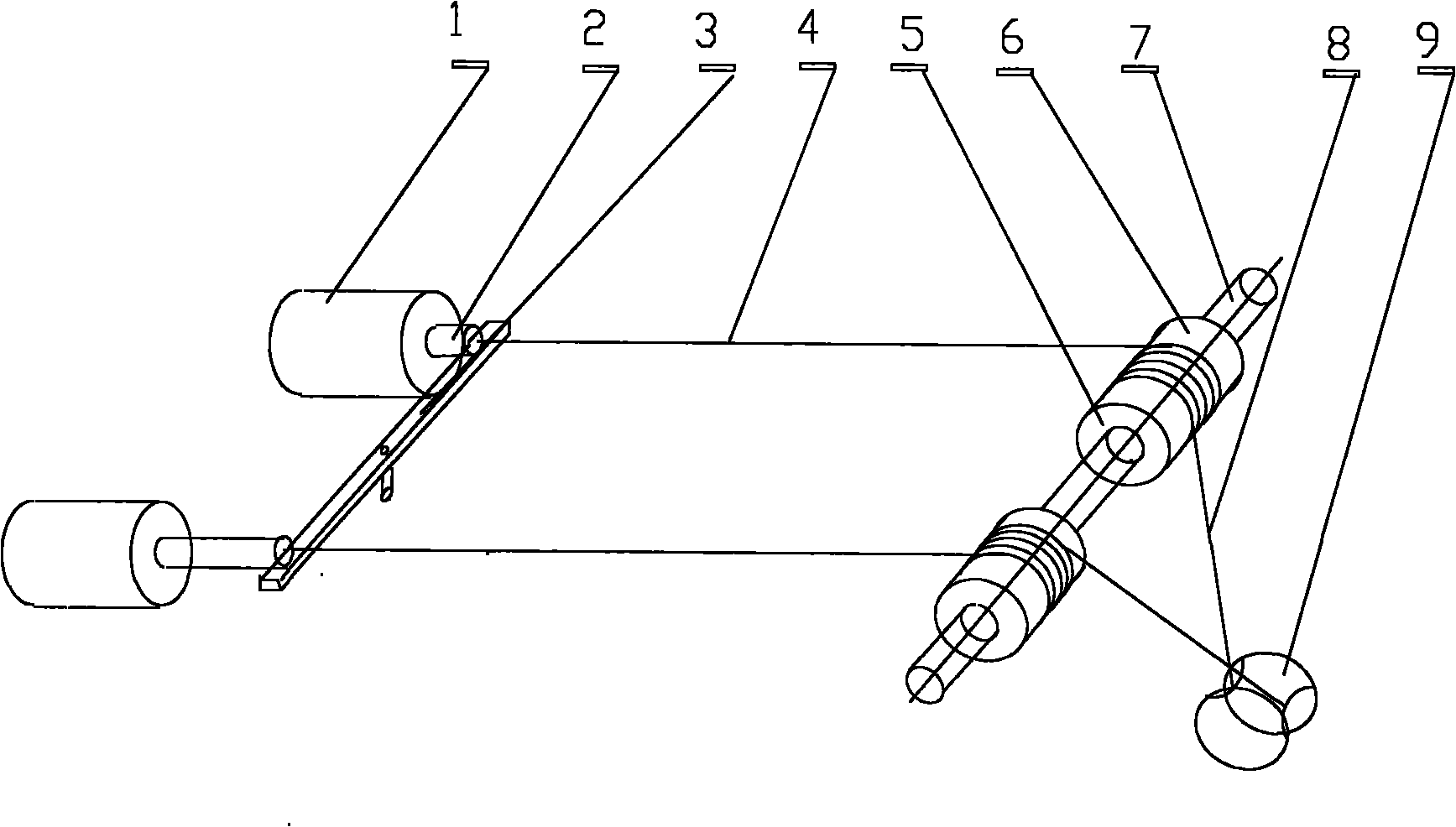
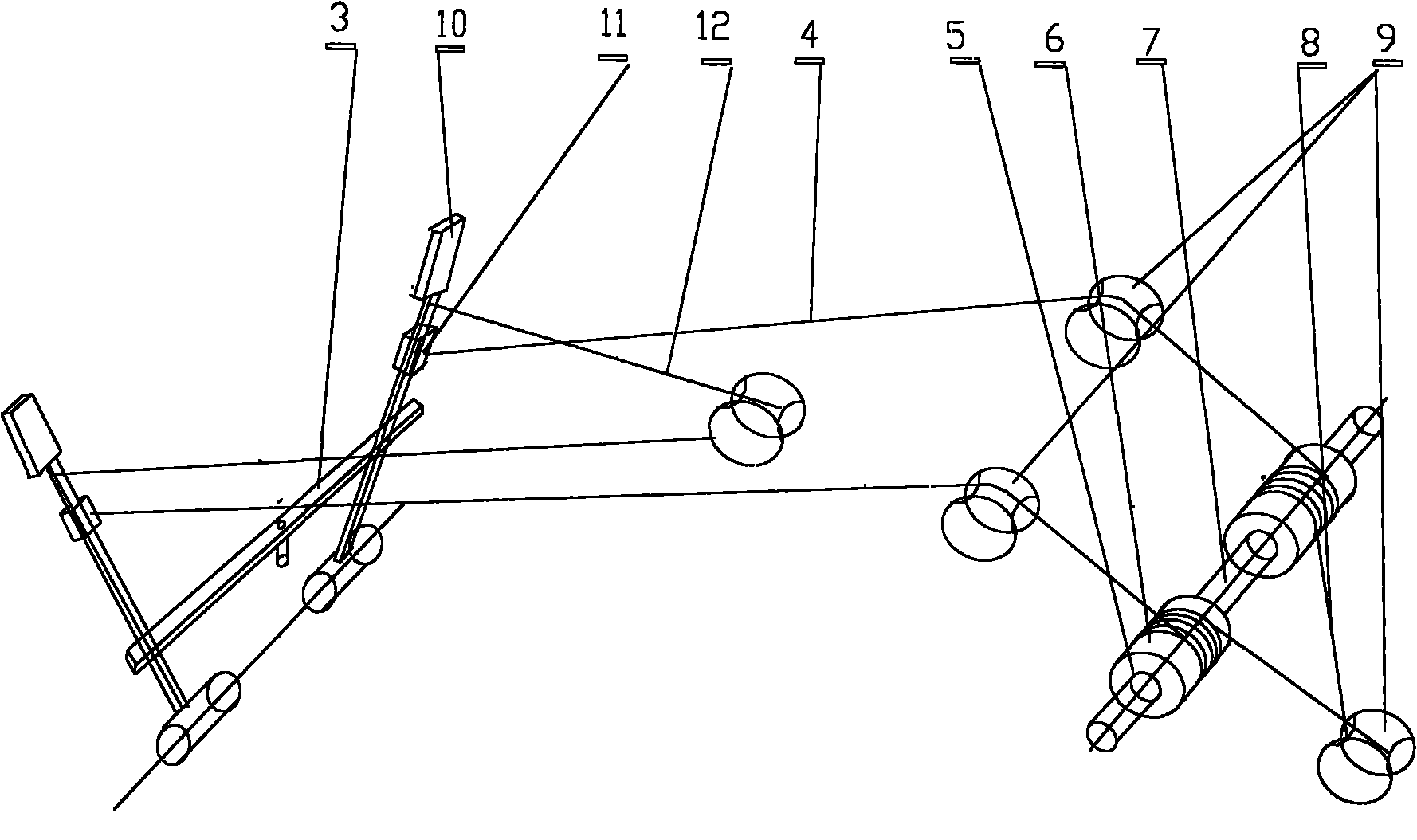
[0027] Attached figure 1 In the reciprocating motion, the power source is the cylinder (1) and the piston (2), which can be driven by compressed air or pressure steam. The two pistons (2) pull the two rope drums (6) to rotate through the rope (4) in turn, and the rope drum ( 6) The power output shaft (7) is driven to rotate through the overrunning clutch (5). The cylinder (1) can be a cylinder powered by compressed air or steam, or it can be a cylinder of an internal combustion engine. The return stroke of the piston (2) does not output power. At this time, the rotation of the rope drum (6) is pulled by a mechanism composed of a rotating cable (8) and a pulley (9).

[0028] Using the rotating rope drum (6) to pass the rope (4), it is also possible to pull the non-working piston (2) back, but the mechanical efficiency of pulling back the ...


PUM


Abstract

The invention discloses a mechanical mechanism which converts reciprocating motion power into rotary power for output and can realize stepless speed regulation. A power source pulls a rope; the rope pulls a rope drum to rotate; and the rope drum drives a power output shaft to rotate through an overrunning clutch; or the power source drives an oscillating bar to oscillate; a rope tractor on the oscillating bar pulls the rope; the rope pulls the rope drum to rotate; and the rope drum drives the power output shaft to rotate through the overrunning clutch. Because the position of the rope tractor on the oscillating bar can be adjusted, the rotating ratio of the moment to the speed between the power source and the power output shaft can be adjusted by adjusting different positions of the rope tractor on the oscillating bar. The mechanical mechanism has the advantages of high efficiency and simple structure, and capacity of realizing the stepless speed regulation; and the power source can be a cylinder or human power or animal power. The mechanical mechanism can be applied to internal combustion engines, bicycles, and other machinery, or can be applied to equipment needing the stepless speed regulation.

Description

technical field [0001] The invention relates to a mechanical mechanism, in particular to a mechanical mechanism that converts reciprocating motion power into rotational power output and can realize stepless speed regulation. Background technique [0002] In mechanical equipment, it is necessary to convert the power source of reciprocating motion into rotational power output in many places. For example, the power source cylinder of internal combustion engine and steam engine is the power for reciprocating motion, and they need to be converted into rotational power output; while human and animal power are trampled as power, It is also reciprocating motion power, which is often converted into rotational power (for example, driving wheels to rotate). Prior art is to realize this conversion with crankshaft linkage mechanism, for example internal combustion engine, steam engine is after cylinder drives crankshaft linkage mechanism, is converted into rotation, manpower is converted...

Claims


Application Information

Patent Timeline
IPC IPC(8): F16H37/12
Inventor 陈悦文陈黎明
Owner 陈悦文
Why Eureka
Try Eureka