Multi-sub-motor coupling planet traction drive bearing type speed reduction driving system

A traction transmission and drive system technology, applied in the direction of electric power unit, power unit, control device, etc., can solve the problems of large loss, large axial size of layout, difficult control, etc., so as to increase mileage and improve work efficiency , the effect of extending the cruising range

Pending Publication Date: 2019-04-16
CHONGQING UNIV
View PDF4 Cites 2 Cited by
  • Summary
  • Abstract
  • Description
  • Claims
  • Application Information

AI Technical Summary

Problems solved by technology

Series connection can realize the optimal control of the engine, but all the energy will be converted twice, and the loss is relatively large; parallel connection can achieve better transmission efficiency, but the mechanical connection between the engine and the output shaft cannot ensure that the engine is always in a better working area ;Hybrid can combine the advantages of series and parallel, and avoid the shortcomings of the two. It is the most optimized configuration among the three; the coupling drive system of the current hybrid hybrid electric vehicle is relatively mature, and the planetary mechanism is mainly used for power coupling. Typical structural forms include Toyota's THS system and GM's AHS system
Among them, Toyota's THS system usually uses a single-row planetary gear mechanism for power coupling; most of GM's AHS systems use a three-row planetary gear mechanism for power coupling, which needs to control multiple clutches and locks for mode switching, resulting in its The structure is complex and difficult to control; and the existing layout has too large axial dimension, too many parts, complex structure and poor reliability
[0004] For pure electric vehicles, there is no effective solution to the coupling of speed and torque;

Method used


Image

  • Multi-sub-motor coupling planet traction drive bearing type speed reduction driving system
  • Multi-sub-motor coupling planet traction drive bearing type speed reduction driving system
  • Multi-sub-motor coupling planet traction drive bearing type speed reduction driving system

Examples


Embodiment Construction

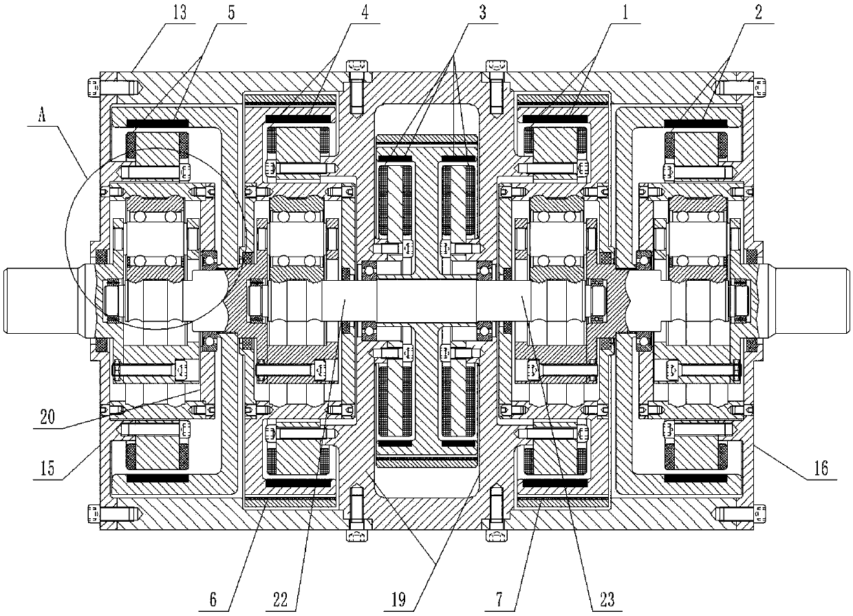
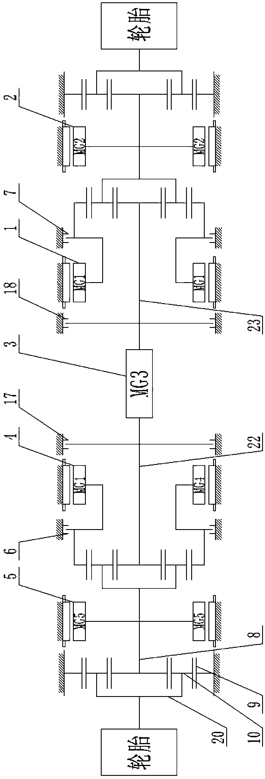
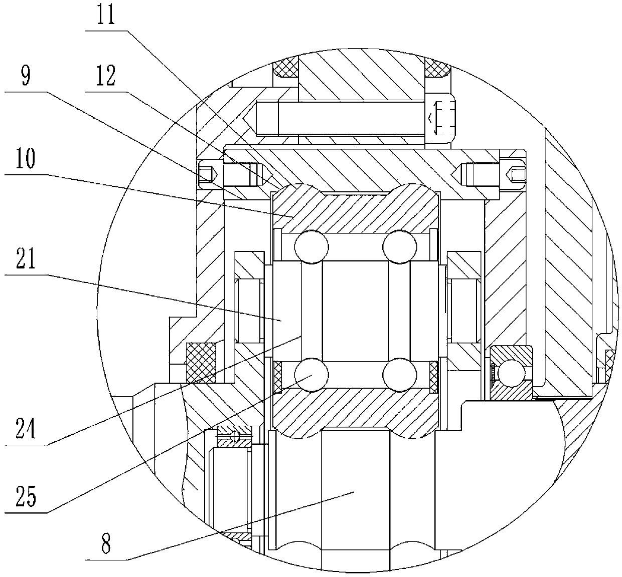
[0033] figure 1 It is a structural schematic diagram of the present invention; figure 2 It is a schematic structural diagram of the principle of the present invention; image 3 for figure 1 Schematic diagram of the enlarged structure at point A; Figure 4 It is a structural schematic diagram of the first cooperation mode between the annular protrusion and the annular channel; Figure 5 It is a structural schematic diagram of the second cooperation mode between the annular protrusion and the annular channel; Figure 6 It is a structural schematic diagram of the third cooperation mode between the annular protrusion and the annular channel;

[0034] In this embodiment, the left and right direction and figure 1 and figure 2 The left and right directions shown are the same, and the real product can have a one-to-one correspondence with the directions in the picture;

[0035] As shown in the figure: including the left planetary traction drive bearing type reducer (hereinaft...


PUM


Abstract

The invention discloses a multi-sub-motor coupling planet traction drive bearing type speed reduction driving system which comprises a left planet traction drive bearing type speed reducer, a right planet traction drive bearing type speed reducer, a number one motor, a number two motor, a number three motor, a number four motor and a number five motor; random order combination of a sun wheel, a planet carrier and an outer ring in the speed reducer is corresponding to a power input end, a power output end and a middle transmission part in the speed reducer respectively, the number three motor is used for providing power, the number one motor and the number four motor are used for speed coupling, and the number two motor and the number five motor are used for torque coupling; according to the multi-sub-motor coupling planet traction drive bearing type speed reduction driving system, through the cooperative working of the four motors, the speed can be coupled so that the wheel high rotation speed or differential speed requirement of two-wheel-drive during turning during vehicle high speed driving can be met, a differential speed device structure is not required to be equipped, the driving system structure is simplified, the structure is compact, and the cost of the driving system is reduced.

Description

technical field [0001] The invention belongs to the technical field of automobile drive, and in particular relates to a multi-motor coupling planetary traction drive bearing type deceleration drive system. Background technique [0002] With the rapid development of the automobile industry, future cars will gradually become hybrid and electrified. At the same time, in order to adapt to the sustainable development of the environment, cars should have lower carbon dioxide emissions and energy consumption. Electric vehicles and hybrid vehicles are currently the most efficient energy-efficient vehicle solutions; [0003] For hybrid electric vehicles, its drive system has three forms: series, parallel and hybrid. Series connection can realize the optimal control of the engine, but all the energy will be converted twice, and the loss is relatively large; parallel connection can achieve better transmission efficiency, but the mechanical connection between the engine and the output...

Claims


Application Information

Patent Timeline
Patent Type & Authority Applications(China)
IPC IPC(8): B60K1/02B60K17/04
CPCB60K1/02B60K17/046
Inventor 舒红宇
Owner CHONGQING UNIV
Why Eureka
Try Eureka