
Gas distribution device for intake system of internal-combustion engine

An air intake system and gas distribution technology, which is applied in the directions of fuel air intake, combustion air/combustion-air treatment, charging system, etc. problems such as uniformity, to achieve the effect of eliminating influence and uniform gas distribution

Inactive Publication Date: 2010-12-15
CHONGQING CHANGAN AUTOMOBILE CO LTD
View PDF2 Cites 6 Cited by
  • Summary
  • Abstract
  • Description
  • Claims
  • Application Information

AI Technical Summary

Problems solved by technology

At present, the common practice is to directly charge the gas to be distributed into the resonant cavity of the intake manifold, and distribute the gas to be distributed into each air channel according to the natural intake characteristics of the intake manifold by the air passing through the resonant cavity, but the existing The problem is: due to the complex air flow inside the resonant cavity of the intake manifold, there are many local air flow vortices, which will cause the air to flow through the resonant cavity to the air passage of the intake manifold due to the resistance generated by the air flow vortex. The phenomenon of uneven gas, which in turn leads to uneven distribution of the gas to be distributed
Moreover, when the air intake volume changes, the gas flow characteristics inside the resonant cavity will also change, and the distribution of the air flow vortex will also change. It is impossible to effectively improve the uniformity of gas distribution by eliminating the air flow vortex design.

Method used


Image

  • Gas distribution device for intake system of internal-combustion engine
  • Gas distribution device for intake system of internal-combustion engine
  • Gas distribution device for intake system of internal-combustion engine

Examples


Embodiment Construction

[0014] The present invention will be further described below with reference to the accompanying drawings and embodiments.

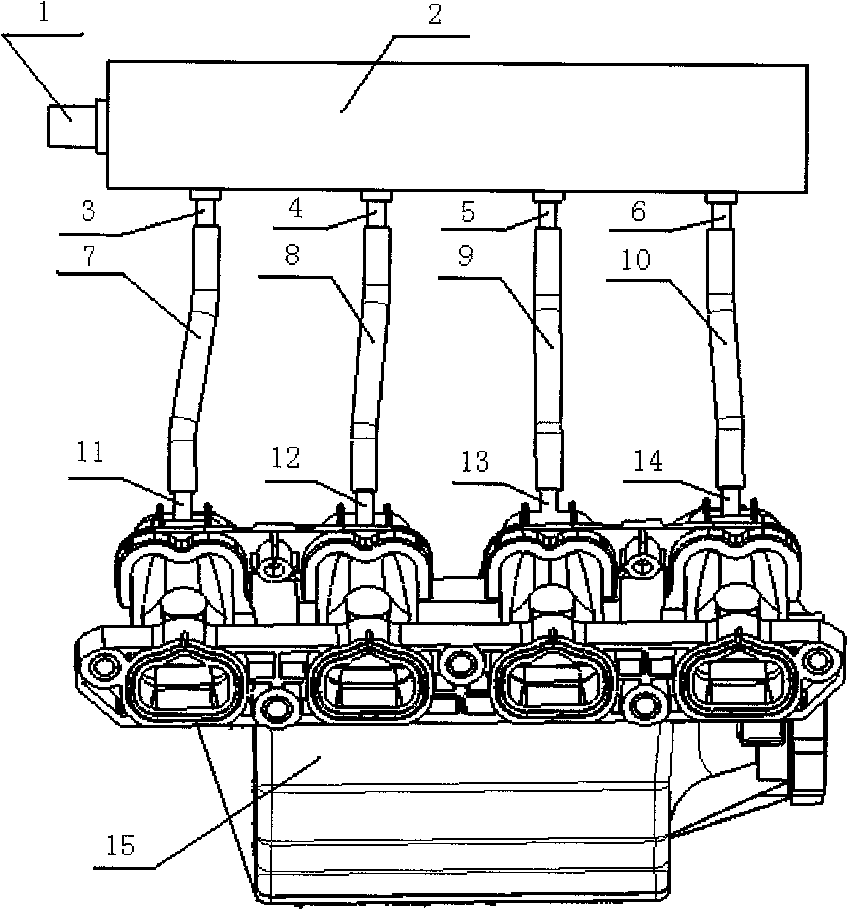
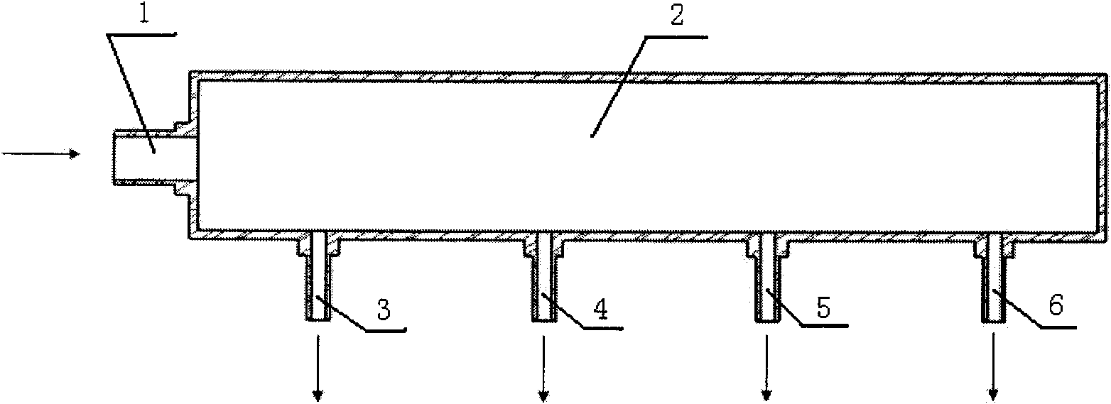
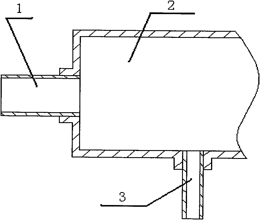
[0015] Implementation one: see figure 1 , figure 2 and Figure 4 , a gas distribution device for an air intake system of an internal combustion engine, comprising a distribution chamber 2, an air inlet port 1 connected to one end of the distribution chamber; Connect with the fourth air outlet 6;

[0016] The first air outlet 3 is connected to the first intake manifold airway interface 11 through the first gas delivery pipe 7; the second air outlet 4 is connected to the second intake manifold airway interface 12 through the second gas delivery pipe 8; The third air outlet port 5 is connected to the third intake manifold air passage port 13 through the third gas delivery pipe 9 ; the fourth air outlet port 6 is connected to the fourth intake manifold air passage port 14 through the fourth gas delivery pipe 10 .

[0017] In this example, the air inlet i...


PUM


Abstract

The invention discloses a gas distribution device for an intake system of an internal-combustion engine. The gas distribution device comprises a distribution cavity and an intake interface connected to one end of the distribution cavity, and is characterized in that: the distribution cavity is connected with a plurality of gas outlet interfaces; each gas outlet connection pipe is connected with an intake manifold gas passage interface through a gas conveying pipe respectively; and the number of the gas outlet interfaces is equal to that of the intake manifold gas passage interfaces. Through the gas distribution device, the idea of directly distributing gas to be distributed to each gas passage of an intake manifold is realized by additionally arranging a device, the influence of air flow in a resonant cavity of the intake manifold on gas distribution is eliminated and uniform gas distribution is realized.

Description

technical field [0001] The invention relates to internal combustion engine components, in particular to a gas distribution device for an intake system of an internal combustion engine. Background technique [0002] In the test of the intake system of the internal combustion engine, it is often necessary to evenly distribute part of the gas to each air passage of the intake manifold to achieve accurate test. The current common practice is to directly charge the gas to be distributed into the resonant cavity of the intake manifold, and the air passing through the resonant cavity distributes the gas to be distributed to each air passage according to the natural air intake characteristics of the intake manifold. The problem is: due to the complex airflow inside the resonant cavity of the intake manifold, there are many airflow vortices locally, which will cause the air to enter the air passages due to the resistance generated by the airflow vortices during the movement of the ai...

Claims


Application Information

Patent Timeline
Patent Type & Authority Applications(China)
IPC IPC(8): F02M35/10F02M35/104
Inventor 鄢烈罗昆郑伟池诚杨占林王冬梅罗凯
Owner CHONGQING CHANGAN AUTOMOBILE CO LTD
Learn More