

Separator rotary feeder and method of using the same
A feeder and rotor technology, applied in the field of devices for separating granular materials and supplying granular materials, can solve the problems of increasing the vertical height of the material processing system, interfering with operations, and complex structural design.
Active Publication Date: 2010-12-15
UNIVATION TECH LLC
View PDF8 Cites 28 Cited by
- Summary
- Abstract
- Description
- Claims
- Application Information
AI Technical Summary
Problems solved by technology
Vibration may interfere with the operation of precision solids metering or feeding devices
Also, since these material handling systems are often gravity fed systems, the installation of screens can also increase the vertical height of the material handling system, increase construction costs and complicate structural design
Method used
View moreImage
Smart ImageViewing Examples

Examples
Embodiment Construction
Login to View More PUM
 Abstract
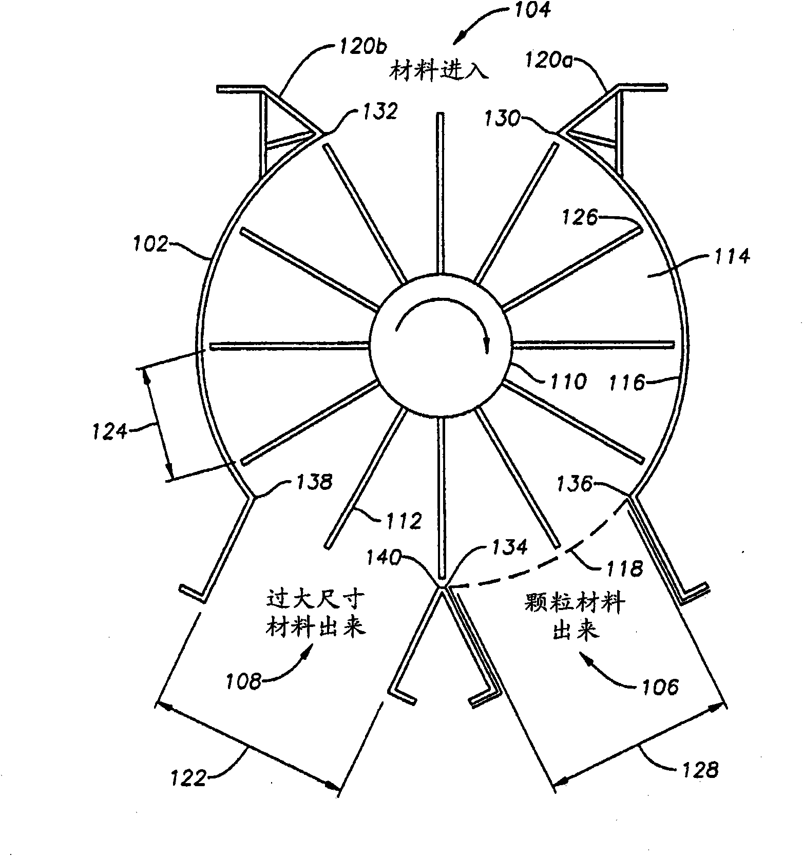
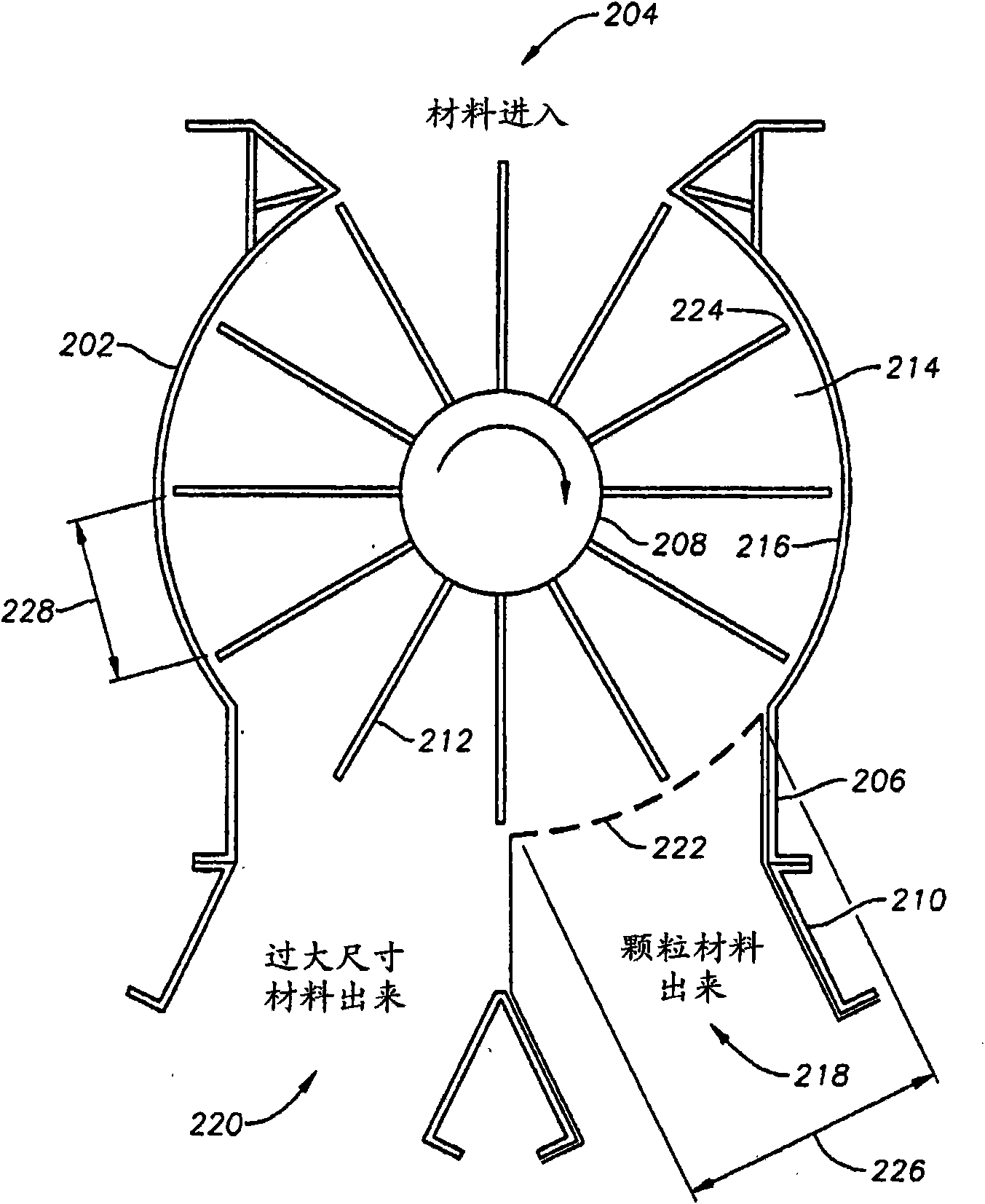
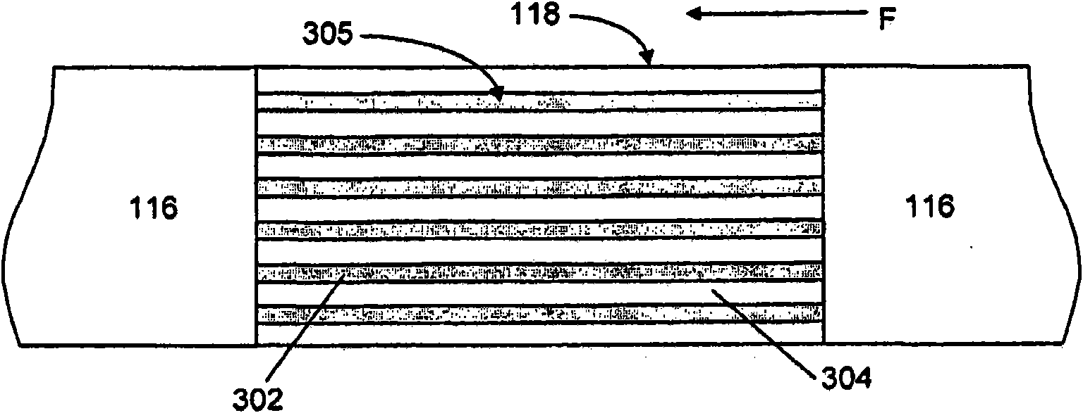
A rotary feeder for feeding a particulate material including: a cylindrical housing comprising a feeder inlet, a first feeder outlet, and a second feeder outlet; a rotor mounted in the cylindrical housing including a plurality of substantially impeller blades defining a plurality of circumferentially spaced pockets alignable with the feeder inlet, first feeder outlet, and second feeder outlet, and adapted to sweep a wall of the cylindrical housing as the rotor rotates in the cylindrical housing; a device for rotating the rotor; and a separating screen in the first feeder outlet to substantially prevent oversize material from exiting through the first feeder outlet, wherein each of the plurality of circumferentially spaced pockets will align with the feeder inlet to receive therein a particulate material and an oversize material through the feeder inlet, rotate in the cylindrical housing to align with the first feeder outlet and discharge the particulate material therefrom, and rotate in the cylindrical housing to align with the second feeder outlet after alignment with the first feeder outlet and discharge the oversized material therefrom is provided as well as a method of using the same.
Description
Cross References to Related Applications This application claims the benefit of No. 61 / 008868, filed December 20, 2007, which is hereby incorporated by reference in its entirety. technical field The present invention generally relates to apparatus and methods for supplying particulate material. More specifically, the present invention relates to the use of a rotary feeder to feed particulate material into a material handling system. The present invention also generally relates to apparatus and methods for separating particulate material in rotary feeders. Background technique Many materials such as plastics, wood chips, grains, shredded waste, granular products, etc. separate materials are processed in material handling equipment using rotary airlock meters or rotary feeders. For example, the separated material may be fed to other solids handling equipment, such as mixers, blenders, or various types of handling vessels. To prevent pressurized gas from escaping or air f...
Claims
Login to View More Application Information
Patent Timeline
 IPC IPC(8): B07B1/20B07B13/07B07B13/16B65G53/46
CPCB07B1/20B07B13/16B07B13/07B65G53/4633
InventorW·J·布里克利R·L·福斯
OwnerUNIVATION TECH LLC