Tile rebate cutting apparatus

一种切割设备、凹榫的技术,应用在贴砖凹榫切割设备领域,能够解决损坏贴砖、难切口精确定位、浪费等问题

Inactive Publication Date: 2010-12-15
丹尼尔·皮尤 +1
View PDF0 Cites 4 Cited by
  • Summary
  • Abstract
  • Description
  • Claims
  • Application Information

AI Technical Summary

Problems solved by technology

The disadvantage of this method is that it is extremely slow and time-consuming to make the necessary cuts, and it is also difficult to ensure that the cuts are precisely positioned, with the result that the tiling can be damaged, resulting in unnecessary waste and at the same time possibly compromising the final appearance of the ceiling
Using sharp knives such as utility knives can be dangerous and is responsible for many accidents

Method used


Image

  • Tile rebate cutting apparatus
  • Tile rebate cutting apparatus
  • Tile rebate cutting apparatus

Examples


Embodiment Construction

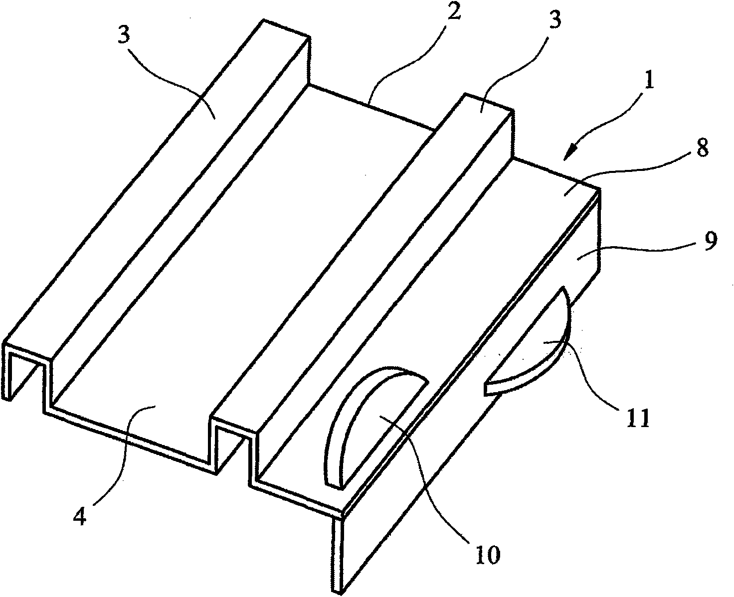
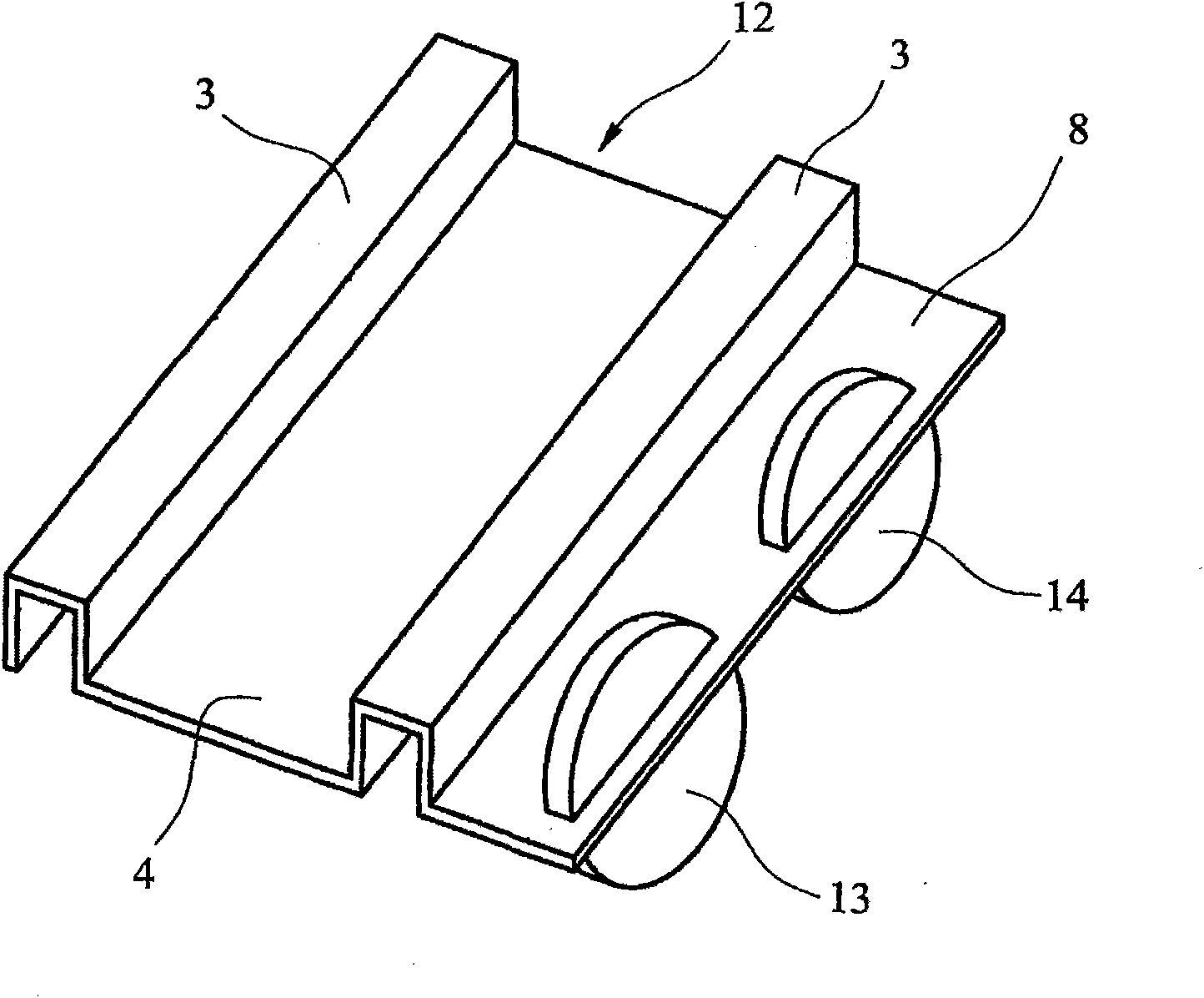
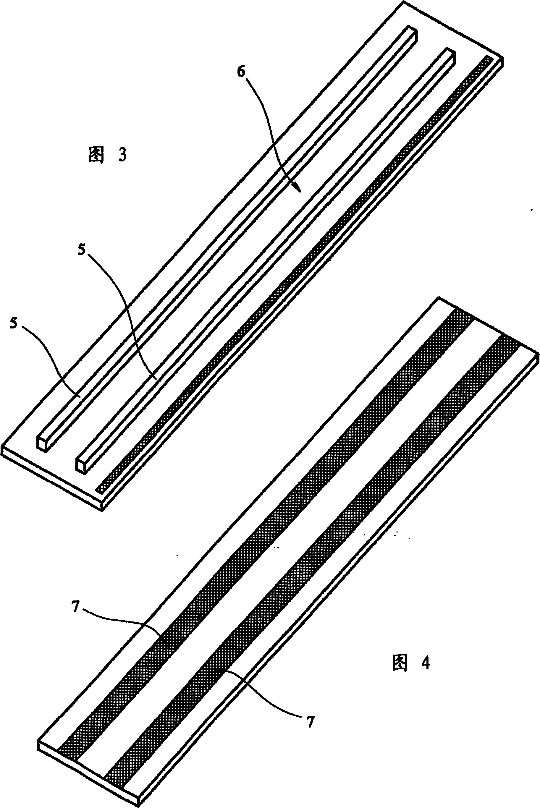
[0027] Referring now to the accompanying drawings Figures 1 to 4 ,exist figure 1 A groove cutting tool 1 is shown in , which is used to cut a groove along one edge of such ceiling tiles, usually formed from foam or expanded plastic material. Said cutting tool 1 consists of a body 2, generally formed of extruded aluminium material, having two downwardly open channels 3 arranged in parallel spaced relation, separated by a base element 4 of the body . The two channels 3 are adapted to engage with two guide rails 5 positioned in parallel spaced relation to the guide member 6 (see image 3 ), the guide member may also be formed from an aluminum extrusion. On its underside, the guide member 6 has a strip 7 of material, such as rubber glued or embedded in the guide member, in order to provide the guide member 6 with a non-slip underside. Many other forms of non-slip surfaces are available.

[0028] Especially as figure 1 As shown, the groove cutting tool 1 has another base ele...


PUM


Abstract

A tile rebate cutting apparatus has a guide member (6), which may be formed by a spirit level, forming a linear guide for a rebate cutting tool (1), the rebate cutting tool incorporating at least one cutting device (10, 11), the rebate cutting tool (1) being adapted to engage with said guide member to move along a predetermined line determined by the position of the guide member (6) to enable a cut for a rebate to be made in a ceiling tile.

Description

technical field [0001] The present invention relates to tile rebate cutting equipment, and more particularly, but not exclusively, to equipment for cutting rebates around the perimeter of ceiling tiles intended for suspended ceilings in offices or the like. Background technique [0002] In such suspended ceilings, a frame formed of aluminum strips is first fastened in the desired position, and then ceiling tiles are placed in the frame to provide a smooth ceiling, and in such ceilings it is also possible to include recessed light fixtures in which all The strips of aluminium described are arranged in a regular pattern to define squares, each square being adapted to receive tiles or panels. Typically, the tiles are only supported on the frame, and in many installations the frame protrudes below the general plane of the tiles. This does not look aesthetically pleasing, so the preferred solution is to provide the tile with a perimeter recess that is supported on the frame so t...

Claims


Application Information

Patent Timeline
Patent Type & Authority Applications(China)
IPC IPC(8): B26B25/00B26B29/06B26D3/06
CPCB28D1/226B28D7/00B26B29/06B27G17/02B28D1/22B28D1/225
Inventor 丹尼尔·皮尤达伦·皮尤
Owner 丹尼尔·皮尤
Why Eureka
Try Eureka