Detonator filling mould and preparation method thereof

A manufacturing method and detonator technology, which are applied to weapon accessories, fuzes, ammunition and other directions, can solve the problems of low work efficiency, increase the complexity of the production line, and difficulty in automatic production, and achieve the advantages of labor-saving and convenient use, convenient removal of detonators, and improved work efficiency. Effect

Active Publication Date: 2010-12-22
GUIZHOU JIULIAN IND EXPLOSIVE MATERIALS DEV
View PDF5 Cites 5 Cited by
  • Summary
  • Abstract
  • Description
  • Claims
  • Application Information

AI Technical Summary

Problems solved by technology

[0002] At present, on the existing detonator production line, the detonator filling mold with bottom plate is generally used to realize the delivery of the tube body in the production process of the detonator. Although this detonator filling mold with bottom plate has the advantages of reliable placement and delivery of detonators, The use of a detonator filling mold with a bottom plate is not conducive to the automatic production of detonator filling. When this kind of detonator filling mold with a bottom plate is used on a detonator production line, the

Method used


Image

  • Detonator filling mould and preparation method thereof
  • Detonator filling mould and preparation method thereof
  • Detonator filling mould and preparation method thereof

Examples


Embodiment 2

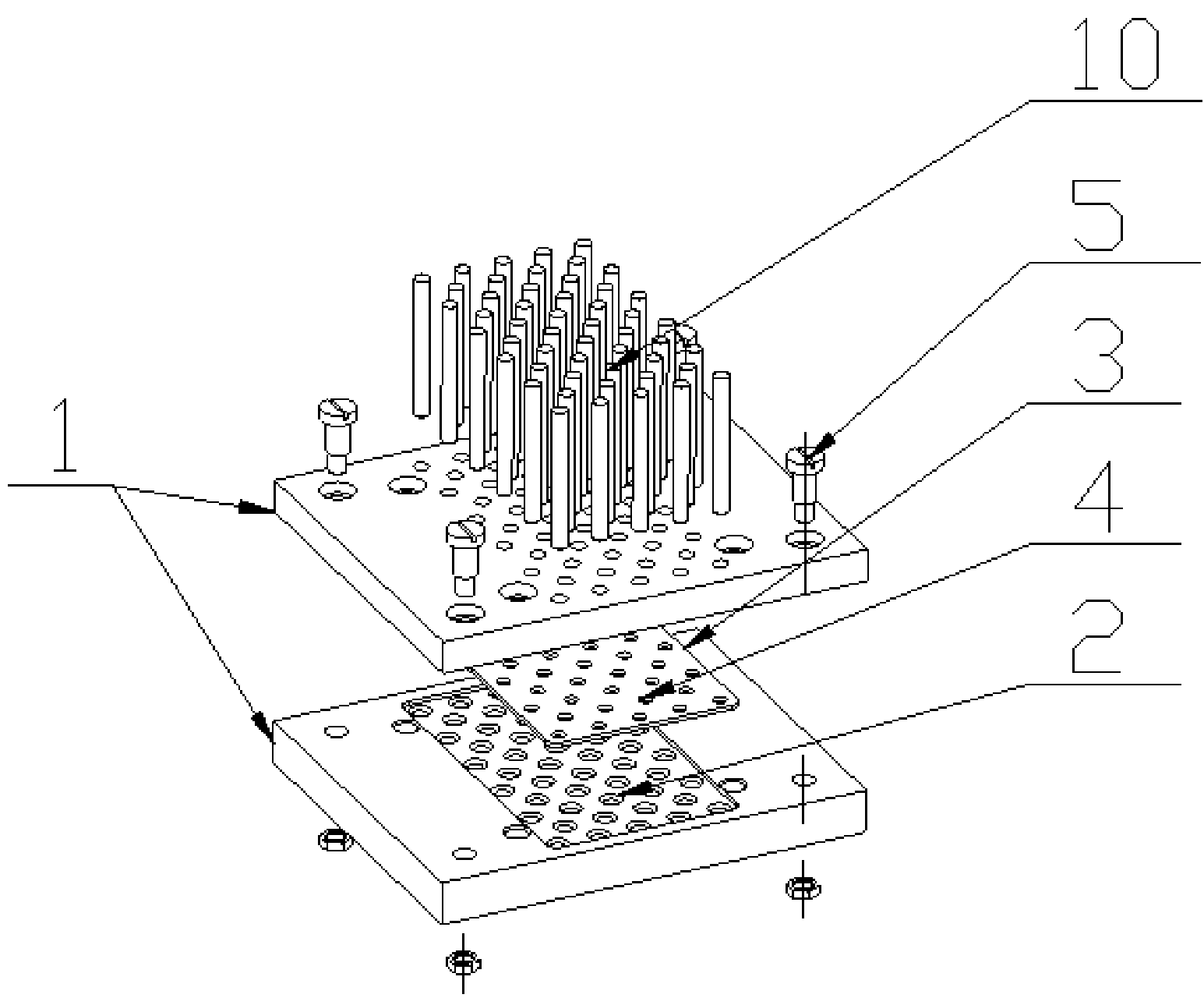
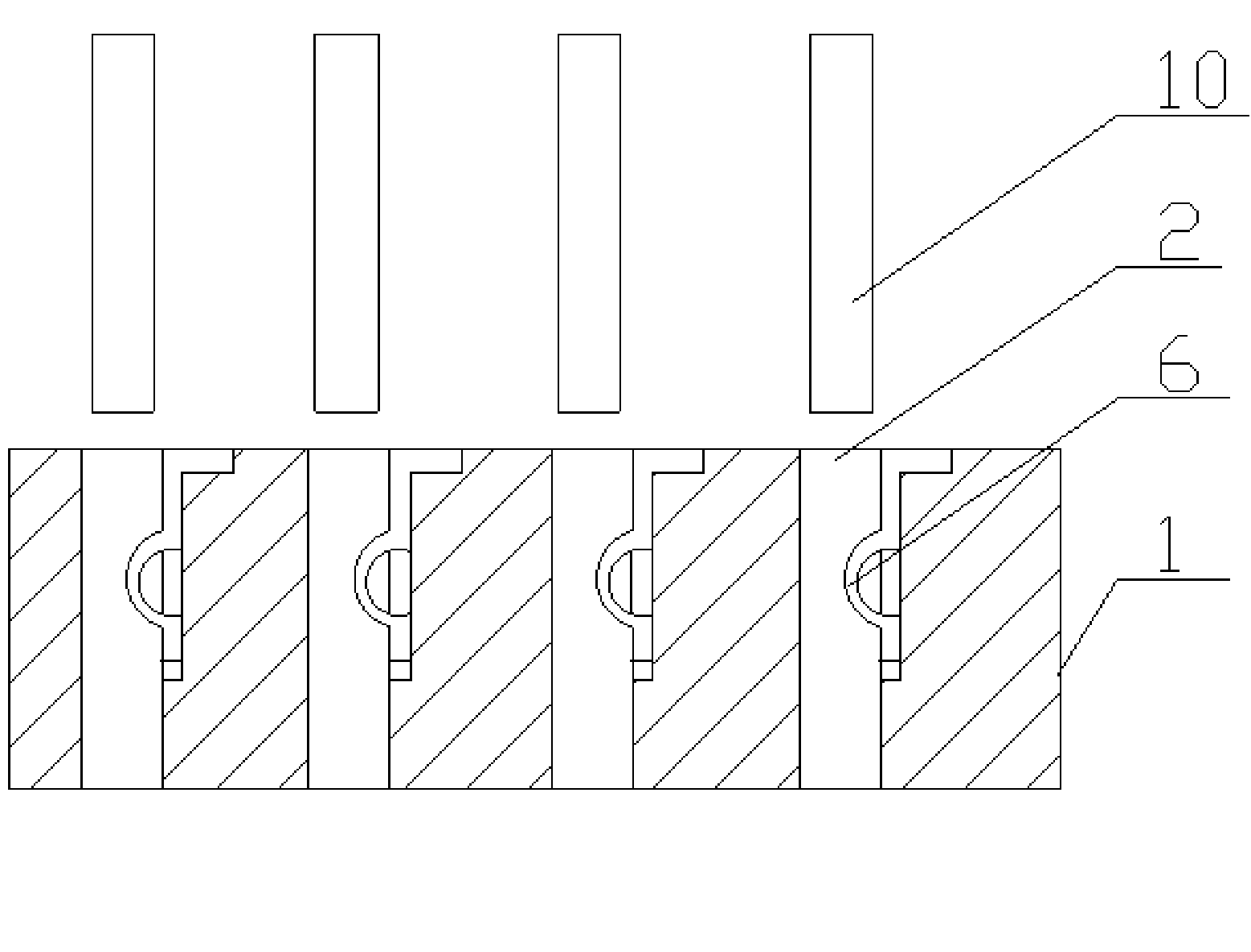
[0017] Embodiment 2 of the present invention: as figure 2 As shown, the quantity of the detonator placement holes 2 on the template 1 is determined according to the scale of production and needs in the traditional way during production, and the detonator placement holes 2 on the template 1 are made as through holes, and then placed in each detonator of the template 1 A piece of elastic sheet 6 as an elastic clamping device is fixed in the hole 2; when fixing the elastic sheet 6, it can be fixed in the detonator placement hole 2 of the template 1 by bonding or screwing, and the elastic sheet 6 can be made of rubber, It can be made of plastic or elastic copper sheet.

Embodiment 3

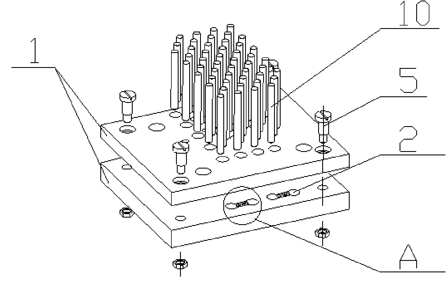
[0018] Embodiment 3 of the present invention: as image 3 As shown, according to the scale of production and the need to determine the number of detonator placement holes 2 on the template 1 during production, the detonator placement holes 2 on the template 1 are all made as through holes, and the template 1 is made by two A flat plate with the same number and the same positions of detonator placement holes 2 is formed, and then on the surface where the two templates 1 are bonded, a half is made on the side of each detonator placement hole 2 by mechanical processing. Circular installation groove 9, spring (7) and ball (8) as elastic fastening device are installed in installation groove 9, and the part spherical surface of each ball 8 protrudes from the inner wall surface of detonator placement hole 2, and then The two formworks 1 are pasted together and connected as a whole by bolts 5 .


PUM


Abstract

The invention discloses a detonator filling mould and a preparation method thereof. The detonator placing holes of the detonator filling mould are prepared into through holes, and an elastic clamping device which can clamp the detonator in a friction mode is arranged in each through hole. In the invention, the traditional detonator filling mould with a bottom plate is changed into a through hole type detonator filling mould, and an elastic clamping device which can clamp the detonator in a friction mode is arranged in each through hole type detonator placing hole, so that the demands of reliably placing the processed detonator are met and the purpose of conveniently taking out the detonator is fulfilled. When the detonator is required to be taken out of the detonator placing hole of the detonator filling mould, the detonator in the hole can be ejected by using an ejector rod below the detonator placing hole. Compared with the prior art, the invention has the advantages that the labor is saved, the operation is convenient, the working efficiency is improved and the invention is applicable to automatic production lines.

Description

technical field [0001] The invention relates to a filling mold for detonator production and a manufacturing method thereof, and belongs to the technical field of detonator production auxiliary tools in the detonator manufacturing industry. Background technique [0002] At present, on the existing detonator production line, the detonator filling mold with bottom plate is generally used to realize the delivery of the tube body in the production process of the detonator. Although this detonator filling mold with bottom plate has the advantages of reliable placement and delivery of detonators, The use of a detonator filling mold with a bottom plate is not conducive to the automatic production of detonator filling. When this kind of detonator filling mold with a bottom plate is used on a detonator production line, the bottom plate and the upper mold must be separated before the tube can be withdrawn. This increases the complexity of the production line and reduces the reliability...

Claims


Application Information

Patent Timeline
IPC IPC(8): F42B33/02F42C19/08
Inventor 占必文聂祥进田禾彭文林聂煜井志明罗贵旭
Owner GUIZHOU JIULIAN IND EXPLOSIVE MATERIALS DEV
Why Eureka
Try Eureka