Switch cabinet door support structure

A switchgear and cabinet door technology, which is applied in building structures, substation/distribution device shells, building fastening devices, etc., can solve problems such as inconvenient switchgear installation and maintenance, and safety hazards on switchgear installation and maintenance sites. , to achieve the effect of convenient manufacture and installation, simple structure, convenient installation and maintenance

Active Publication Date: 2010-12-22
镇江船舶电器有限责任公司
View PDF4 Cites 11 Cited by
  • Summary
  • Abstract
  • Description
  • Claims
  • Application Information

AI Technical Summary

Problems solved by technology

[0002] In the existing switchgear, the cabinet door is usually in a state of free rotation around the hinge after opening, which is not convenient fo

Method used


Image

  • Switch cabinet door support structure
  • Switch cabinet door support structure
  • Switch cabinet door support structure

Examples


Embodiment Construction

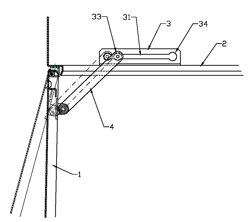
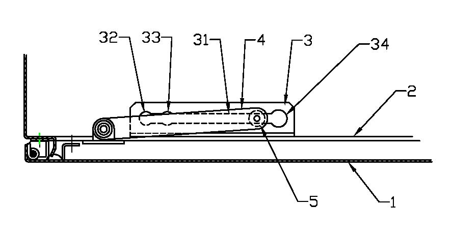
[0013] As shown in the figure, the switch cabinet door support structure includes a cabinet door 1 connected to the switch cabinet door frame through a hinge; a horizontal positioning plate 3 is fixed on the horizontal beam 2 of the switch cabinet door frame, and the positioning plate A linear guide groove 31 is arranged on the top, and the rear end of the linear guide groove is provided with an end positioning hole 32 whose diameter is greater than the width of the linear guide groove. Hole 33; a horizontal connecting rod 4 is arranged on the inner side of the cabinet door 1, the rear end of the connecting rod is hinged with the cabinet door, and the front end of the connecting rod is connected with a column pin 5 with a vertical central axis; the column pin is divided into diameters from top to bottom. The different four sections are successively the upper limit section 51, the positioning section 52, the guide section 53, and the lower limit section 54, wherein the diameter ...


PUM


Abstract

The invention relates to an accessory structure of power transmission equipment, in particular to a switch cabinet door support structure used for locating the opening state of the switch cabinet door. The structure is characterized in that a locating plate is fixed on a horizontal beam of a switch cabinet door frame; a straight groove is arranged on the locating plate; a locating hole is arranged at the rear end of the straight groove; a connecting rod is arranged at the inner side of the cabinet door; the rear end of the connecting rod is hinged with the cabinet door and the front end thereof is connected with a pin; the pin is divided into an upper limiting segment, a locating segment, a guiding segment and a lower limiting segment from top to bottom; the diameter of the upper limiting segment is more than that of the locating hole at the end; the diameter of the locating segment is less than that of the locating hole at the end and more than the width of the straight groove; the diameter of the guiding segment is less than the width of the straight groove; the diameter of the lower limiting segment is more than that of the locating hole at the end; and the pin passes through the locating plate and the guiding segment of the pin can slide along the straight groove. The structure has simple structure, is convenient to manufacture and install, not only facilitates installation and maintenance of the switch cabinets but also eliminates the potential safety hazards of field installation and maintenance.

Description

technical field [0001] The invention relates to an accessory structure of power transmission equipment, in particular to a switch cabinet door support structure for positioning the open state of the switch cabinet door. Background technique [0002] In the existing switchgear, the cabinet door is usually in a state of free rotation around the hinge after opening, which is not convenient for the installation and maintenance of the switchgear, and is likely to bring safety hazards to the installation and maintenance site of the switchgear. Contents of the invention [0003] The technical problem to be solved by the present invention is to provide a switchgear door support structure with simple structure, reliable positioning, multi-level positioning and convenient operation. [0004] The switch cabinet door support structure of the present invention comprises a cabinet door connected to the door frame of the switch cabinet body through a hinge; a horizontal positioning plate...

Claims


Application Information

Patent Timeline
IPC IPC(8): H02B1/26E05C17/12
Inventor 眭六云
Owner 镇江船舶电器有限责任公司
Why Eureka
Try Eureka