


Quick Research
Generate reliable direction feasibility study reports for your R&D in just a few steps.

Technical Q&A
Discover and master advanced knowledge NOW. Basics, ideas, possibilities, all at once.

Find Solutions
As an expert in R&D theories, this can generate solutions to your technical problems instantly.

Evaluate Feasibility
Analyze your overall solution with one click, know your potential R&D risks in advance.

Monitor Landscape
Get weekly tech updates, stay abreast of the latest tech innovations and key insights.
Method, device and system for optimizing ISR (Information Storage and Retrieval)
An optimization method and technology of an optimization device, which are applied in the field of ISR optimization, can solve the problems of reducing the utilization efficiency of network resources and the limitation of ISR functions, and achieve the effects of improving the utilization rate of network resources and optimizing the signaling structure.
- Summary
- Abstract
- Description
- Claims
- Application Information
AI Technical Summary
Problems solved by technology
Method used
Image

Examples
Embodiment 1
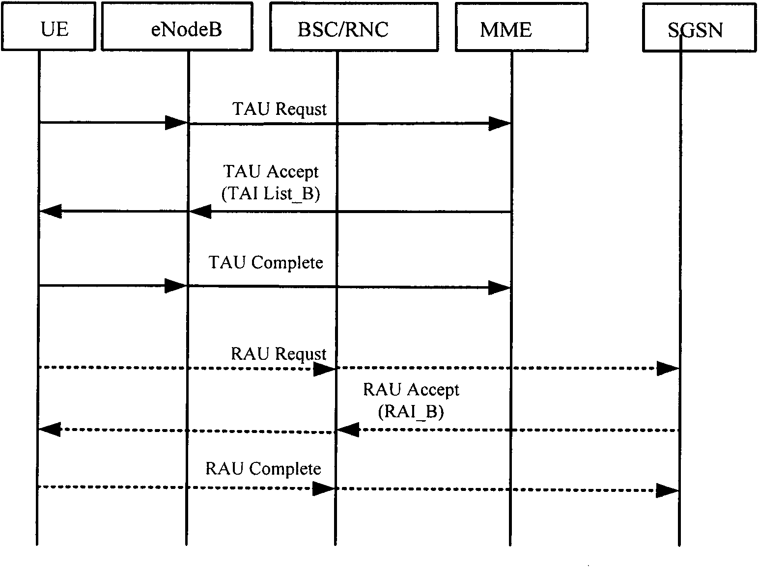
[0045] Figure 4 This is a flowchart of an ISR optimization method according to Embodiment 1 of the present invention. like Figure 4 As shown, when the UE performs location update in the network, this embodiment includes:
[0046] Step S102: Pre-store the mapping relationship between TAI List and RAI;
[0047] Step S104: Receive a location update request initiated by the UE forwarded by the base station;
[0048] Step S106: Allocate the TAI List_B corresponding to the current location to the UE, and obtain the RAI_B corresponding to the TAI List_B according to the mapping relationship between the TAIList and the RAI;
[0049] Step S108: The base station sends a location update response to the UE, the location update response includes the information of TAI List_B and RAI_B, and instructs the UE to perform location area update according to the information of TAI List_B and RAI_B.
[0050] The ISR optimization method in this embodiment can be applied to the E-UTRAN network....
Embodiment 2
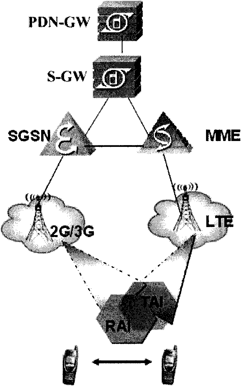
[0055] Figure 5 This is a schematic diagram of an application scenario of the ISR optimization method according to the second embodiment of the present invention. like Figure 5 As shown, the UE is under the coverage of the E-UTRAN network, its ISR is active, and the P a Location and P b The location is located in the location management area of the same MME. UE is first located at P a The location is within the coverage of the E-UTRAN network TAI List_A. The UE stores the information of TAIList_A and RAI_A, and TAI List_A includes TAI a1 , TAI a2 , TAI a3 , TAI a4 Four tracking areas; then move to P b location, P b The location is within the coverage of TAI List_B, only TAI is given for clarity b1 a tracking area. In the above scenario, a static mapping table of the mapping relationship between TAI List and RAI is pre-stored in the MME or related entities. Image 6 This is a flowchart of an ISR optimization method in an E-UTRAN network according to Embodiment ...
Embodiment 3
[0072] Figure 7 This is a flowchart of the third embodiment of the present invention ISR optimization method. like Figure 7 As shown, when the UE performs location update in the network, this embodiment includes:
[0073] Step S302: Pre-store the mapping relationship between RAI and TAI List;
[0074] Step S304: Receive a location update request initiated by the UE forwarded by the base station;
[0075] Step S306: Allocate the RAIcB corresponding to the current location to the UE, and obtain the TAI List_B corresponding to the RAI_B according to the mapping relationship between the RAI and the TAI List;
[0076] Step S308: The base station sends a location update response to the UE, the location update response includes the information of RAI_B and TAI List_B, and instructs the UE to perform location area update according to the information of RAI_B and TAI List_B.
[0077] The ISR optimization method in this embodiment can be applied to a UTRAN / GERAN network. In this ...
PUM
 Abstract
Description
Claims
Application Information
 - R&D Engineer
- R&D Manager
- IP Professional
- Industry Leading Data Capabilities
- Powerful AI technology
- Patent DNA Extraction
Browse by: Latest US Patents, China's latest patents, Technical Efficacy Thesaurus, Application Domain, Technology Topic, Popular Technical Reports.
© 2024 PatSnap. All rights reserved.Legal|Privacy policy|Modern Slavery Act Transparency Statement|Sitemap|About US| Contact US: help@patsnap.com