Pneumatic constant pressure valve

A technology of constant pressure valve and valve body, which is applied to valve details, safety valves, balance valves, etc., and can solve problems such as poor pressure stabilization effect and fluctuating range of the liquid outlet.

Active Publication Date: 2013-01-30
上海远安流体设备科技有限公司
View PDF1 Cites 1 Cited by
  • Summary
  • Abstract
  • Description
  • Claims
  • Application Information

AI Technical Summary

Problems solved by technology

[0005] For this reason, the technical problem to be solved by the present invention is: to overcome the technical defects of the prior art that the pressure of the liquid outlet is in a fluctuating range and the effect of stabilizing the pressure is not good, thereby providing a stabilizing valve with a good effect of stabilizing the pressure;

Method used


Image

  • Pneumatic constant pressure valve
  • Pneumatic constant pressure valve
  • Pneumatic constant pressure valve

Examples


Embodiment 1

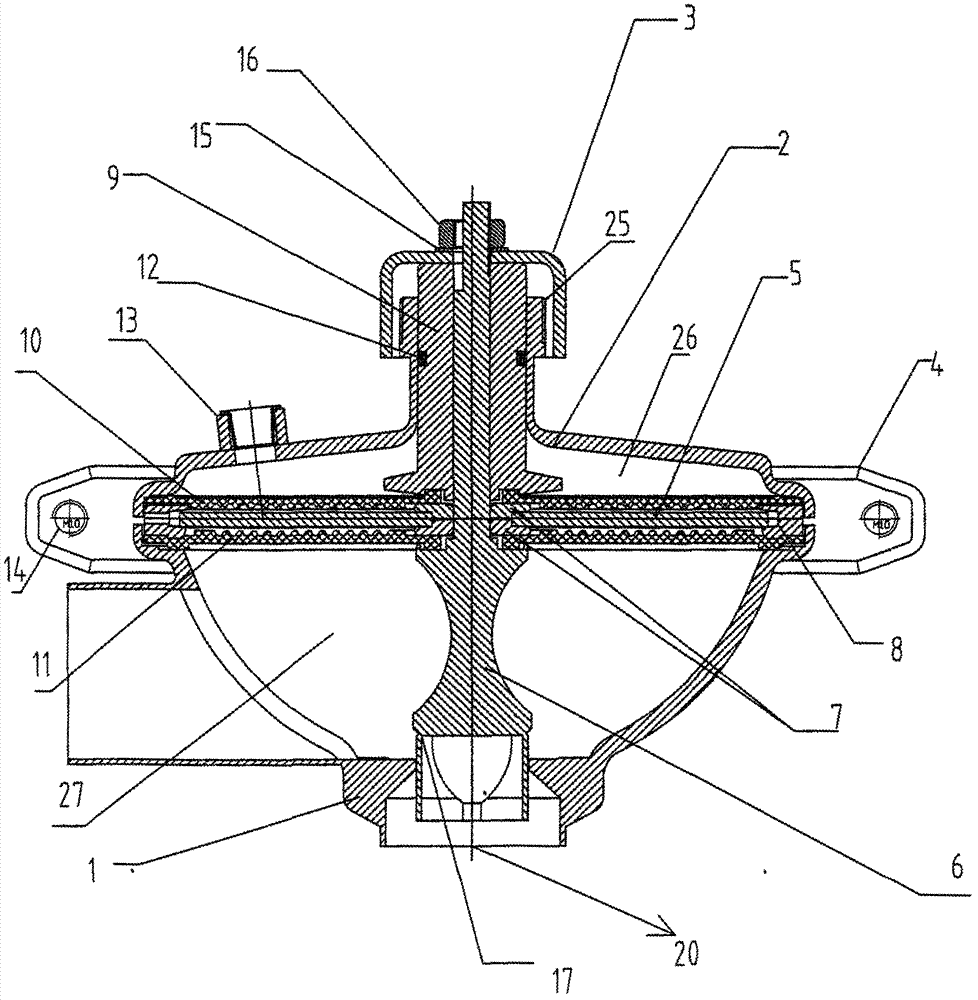
[0031] see figure 1 , the pneumatic constant pressure valve in this embodiment includes: a concave valve body 1, the valve body 1 has a mounting edge, and a liquid outlet is provided at the center of the bottom of the valve body 1, and the liquid outlet is connected with a pressure detection device 20 The side wall of the valve body 1 has a liquid inlet in the horizontal direction; the installation edge of the valve body 1 passes through two semicircular clamps 4 with a U-shaped cross-section and an inner groove and a concave The mounting edge of the bonnet 2 is sealed and fixed, wherein two semicircular clamps 4 are fixedly connected by hexagon socket nuts 14; an air inlet is provided on the bonnet 2, and the air inlet is connected to an air source control The device 13 is connected; between the mounting edge of the valve body 1 and the valve cover 2, the edge of a sealing diaphragm is sealed and fixed, and an elastic sealing air cavity 26 is formed between the sealing diaphr...

Embodiment 2

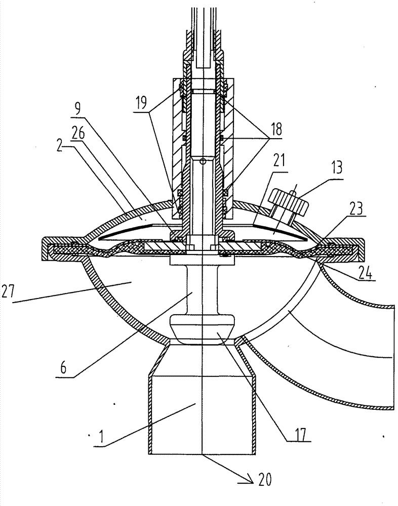
[0037] see figure 2 . The pneumatic constant pressure valve of the present invention includes a valve body 1 , which is concave, and the cross section of the valve body 1 is circular here, and may also be set as an ellipse. The valve body 1 has a valve body installation edge, a liquid outlet is provided at the center, and a liquid inlet is arranged next to the liquid outlet, and the liquid inlet here is arc-shaped; the valve cover 2 is concave , with the installation edge of the valve cover 2 matching with the connection structure of the installation edge of the valve body 1, a hollow installation pipe 25 is fixedly arranged in the center of the valve cover 2 at a position corresponding to the liquid outlet, and the hollow The installation pipe 25 passes through the middle of the valve cover 2, and is axially aligned with the center of the liquid outlet; the valve cover 2 is also provided with an air source control device 13 connected to the air inlet, sealing the diaphragm ...


PUM


Abstract

The invention relates to a pneumatic constant pressure valve which comprises a valve body and a valve cap, wherein the valve cap is hermetically matched with the valve body; a sealing diaphragm is arranged between the valve body and the valve cap, the outer edge of the sealing diaphragm is clamped between the valve body and the valve cap, the rest part of the sealing diaphragm can move up and down in the working state, and a through hole is arranged in the middle of the sealing diaphragm; an air inlet and an air inlet standard part 1 for sealing the air inlet are arranged on the valve cap; a through hole is arranged in the middle of the valve cap; a liquid inlet on the side wall and a liquid outlet on the bottom are arranged on the valve body; a valve spool rod hermetically passes through the through hole of the valve cap and the through hole of the sealing diaphragm and extends into the valve body; a valve plug hermetically matched with the liquid outlet is arranged at the lower end of the valve spool rod; and when the sealing diaphragm moves upwards, the valve spool rod is driven by a link mechanism to move upwards to separate the valve plug from the liquid outlet. The pneumatic constant pressure valve of the invention adapts to the requirements of large scale production, can realize opening of the valve and control of the liquid flow and liquid pressure at the outlet under the working state of the valve without frequently replacing components, simultaneously has good pressure stabilizing effect, and can adapt to different liquid environments.

Description

technical field [0001] The invention relates to a valve, in particular to a pneumatic constant pressure valve used in the manufacturing process of hygienic products such as beer, beverage and medicine. Background technique [0002] As a relay control structure in the process of fluid distribution, valves are widely used in the production and manufacturing of sanitary products such as beer, beverages and medicines. Chinese patent document CN2474848Y discloses a liquid pressure stabilizing valve, which includes a housing, a water inlet and a water outlet at both ends of the housing, a sealing cover is installed on the upper end of the housing, a pressure adjusting nut is installed in the middle of the sealing cover, the sealing cover and the housing A rubber septum is installed in the liquid seal between the rubber septa, a rubber septum reinforcement plate is installed on the upper surface of the rubber septum, a connecting rod is installed on the liquid seal of the rubber se...

Claims


Application Information

Patent Timeline
Patent Type & Authority Patents(China)
IPC IPC(8): F16K17/00F16K27/00F16K31/126
Inventor 项少聪
Owner 上海远安流体设备科技有限公司
Why Eureka
Try Eureka