Fryer convenient for fetching and placing frying cage

A frying pan and convenient technology, which can be applied to the utensils for frying things in oil, oil/fat baking, household utensils, etc., can solve the problems of inconvenient access to the frying basket, etc., and achieve ingenious design, simple structure and convenience. Practical pick and place effect

Active Publication Date: 2012-08-22
MIDEA GRP CO LTD
View PDF1 Cites 0 Cited by
  • Summary
  • Abstract
  • Description
  • Claims
  • Application Information

AI Technical Summary

Problems solved by technology

The disadvantage of this structure is: when the internal gear is below the frying basket gear (below the rotation axis), it is necessary to set a through hole on the side wall of the inner pot to install the gear shaft. , high-temperature oil is easy to overflow from the through hole; when the internal gear is above the frying basket gear (above the rotation axis), there is no need to set a through hole on the inner pot, but the internal gear interferes with the frying basket gear, and the frying basket cannot be conveniently carried out. pick and place

Method used


Image

  • Fryer convenient for fetching and placing frying cage
  • Fryer convenient for fetching and placing frying cage
  • Fryer convenient for fetching and placing frying cage

Examples


Embodiment

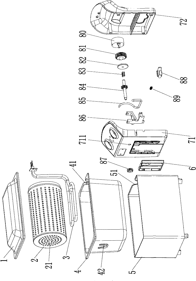
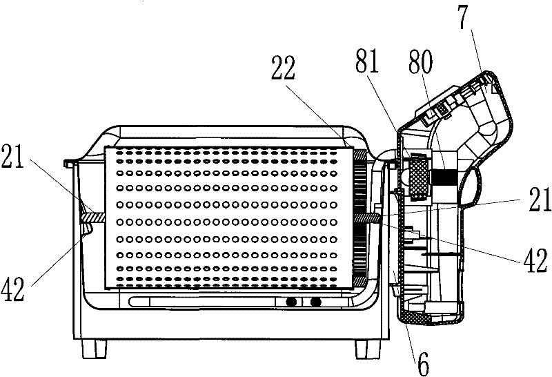
[0035] The structure diagram of the present invention is as figure 1 , 2 , 3, and 4, the fryer in this embodiment includes a loam cake 1, a frying cage 2, a heater 3, an inner pot 4, an outer shell 5 and a control box 7, the inner pot 4 is placed in the outer shell 5, and the heater 3 is placed On the inner bottom of the inner pot 4 (the outer bottom is also acceptable), the frying basket 2 is placed in the inner pot 4, and the control box 7 is formed by buckling the control box cover 71 and the control box seat 72, and is detachably fixed by the support seat 6 on the housing side wall. Control elements (not shown) such as driving mechanism 8 and thermostat, timer are installed in the control box 7.

[0036] Steps 42 protruding toward the center of the inner pot are respectively provided on the two side walls of the above-mentioned inner pot 4 facing the control box, and support shafts 21 are respectively provided at both ends of the frying cage 2, and the two support shafts...


PUM


Abstract

The invention discloses a fryer convenient for fetching and placing a frying cage. The fryer comprises an upper cover, a frying cage, a heater, an inner pan, a shell and a drive mechanism, wherein the inner pan is arranged in the shell; the heater is arranged at the bottom of the inner pan; the frying cage is arranged in the inner pan; the upper cover is arranged at the upper end of the shell; one end of the frying cage is provided with a frying cage gear ring; the drive mechanism comprises a motor, a driving shaft and driven teeth fixed at the end of the driving shaft, wherein the motor and the driving shaft are arranged on the shell, the driven teeth at the end of the driving shaft are engaged with the frying cage gear ring, the output shaft of the motor is provided with driving teeth, and the driving shaft is provided with a gear engaged with the driving teeth; and the drive mechanism also comprises a control device for driving the driving shaft to move along the axial direction and controlling whether the driven teeth at the end of the driving shaft are engaged with the frying cage gear ring. The fryer converts an external force into contraction power of the driving shaft by using a transmission device so that the driving shaft has a structure of contracting as required, the engagement state of a driven gear and a frying cage gear is released, the interference of the driving shaft to the frying cage is released, and the frying cage is convenient to fetch and place.

Description

technical field [0001] The invention relates to a deep fryer with easy access to a frying basket, which belongs to the transformation technology of a fryer with a convenient removal and placement of a frying cage. Background technique [0002] Chinese patent "ZL03273400.X electric fryer with rotatable fryer basket" discloses a fryer with a fryer basket that can be rotated 360°, saves fuel, and can make food fry better. The gear shaft passes through the side wall of the inner pot The inner gear and the outer gear are respectively fixed at both ends, the frying basket gear fixed at one end of the fryer meshes with the inner gear, the driving gear fixed on the motor shaft meshes with the outer gear, and the fryer basket is driven by the motor to rotate. The disadvantage of this structure is: when the internal gear is below the frying basket gear (below the rotation axis), it is necessary to set a through hole on the side wall of the inner pot to install the gear shaft. , high-...

Claims


Application Information

Patent Timeline
Patent Type & Authority Patents(China)
IPC IPC(8): A47J37/12A21B5/08
Inventor 杨云冯敏强高天兵
Owner MIDEA GRP CO LTD
Why Eureka
Try Eureka