
Cooling device for vehicle

A technology for cooling devices and vehicles, which is applied to the arrangement of the parts of the pumping device for elastic fluid, the cooling of the engine, and the cooling of the power plant, etc., which can solve the problems of driver irritability and reduce the sound of the segment Effect

Inactive Publication Date: 2011-01-05
HYUNDAI MOTOR CO LTD +1
View PDF1 Cites 5 Cited by
  • Summary
  • Abstract
  • Description
  • Claims
  • Application Information

AI Technical Summary

Problems solved by technology

Also, segmental sounds can cause a high frequency "hum" in the vehicle, which can annoy the driver

Method used


Image

  • Cooling device for vehicle
  • Cooling device for vehicle
  • Cooling device for vehicle

Examples


Embodiment Construction

[0024] Exemplary embodiments of the present invention will now be described in detail with reference to the accompanying drawings.

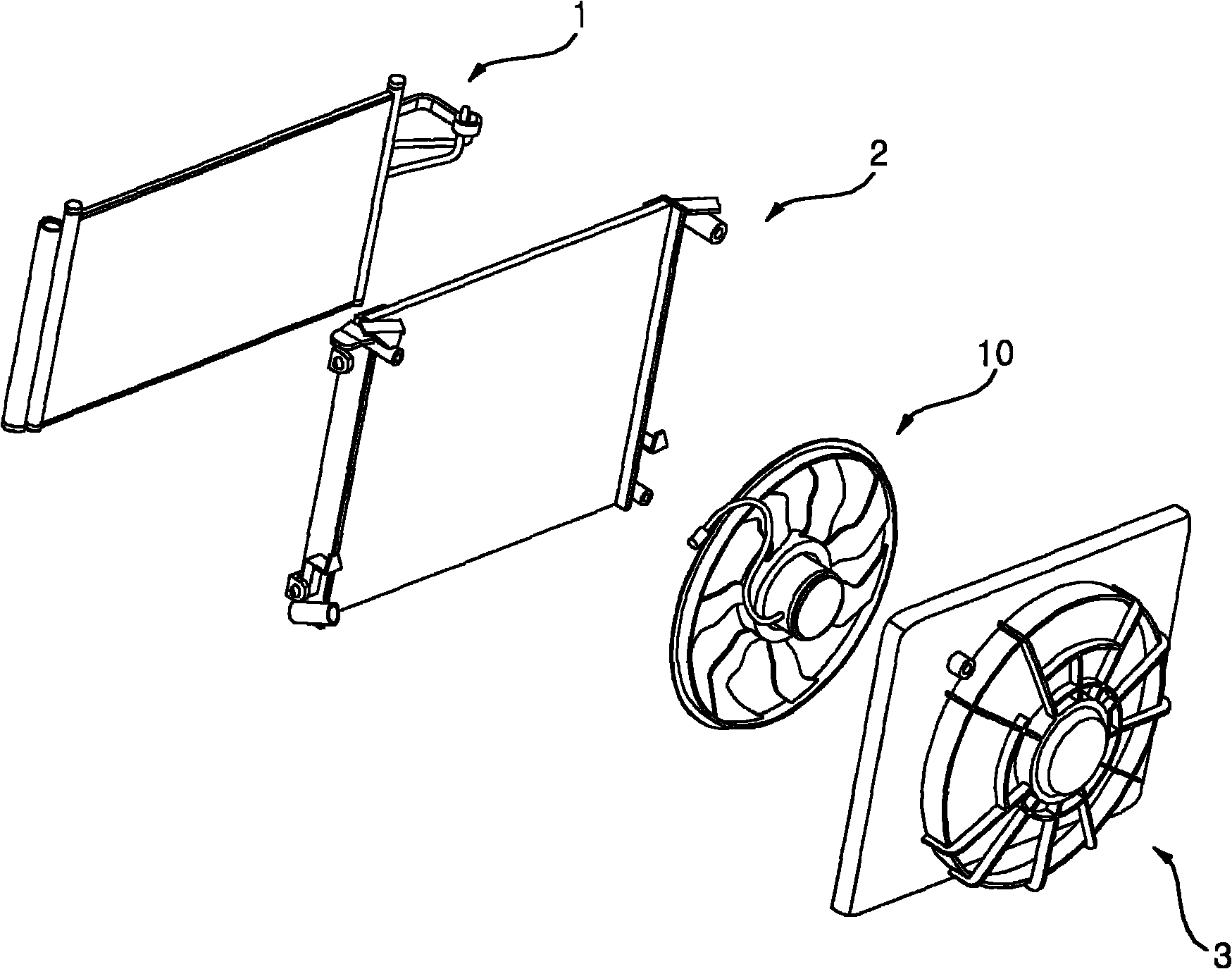
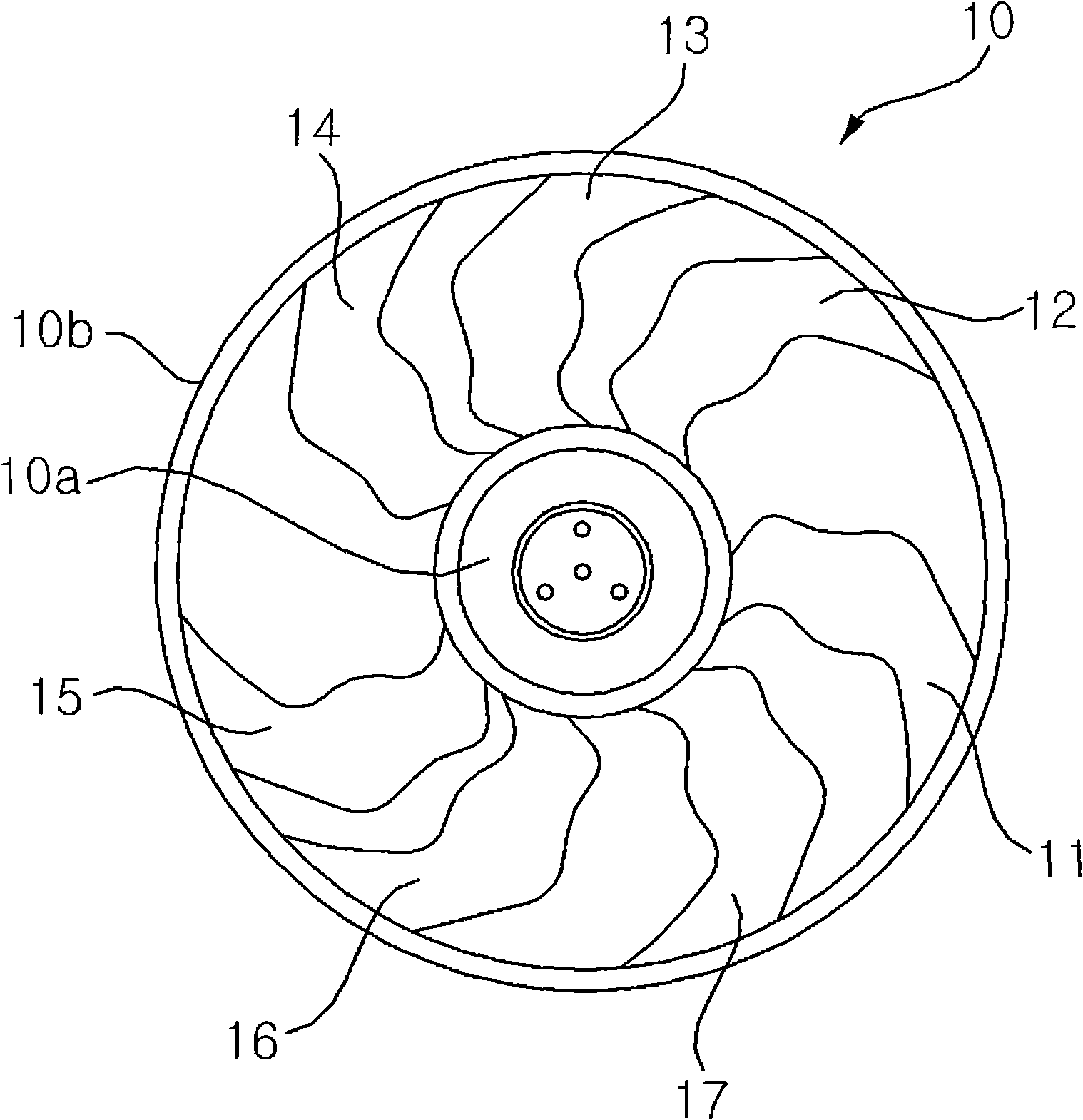
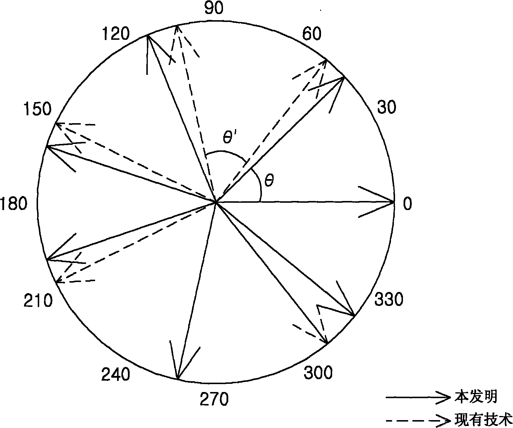
[0025] figure 1 is an exploded perspective view showing a cooling device for a vehicle according to an exemplary embodiment of the present invention, figure 2 is shown figure 1 Front view of the cooling fan shown, image 3 is shown in vector notation figure 2 A view of the multiple blades in the cooling fan shown, and Figure 4 is used to be used by figure 1 The graph shown compares the noise generated by a cooling fan with the noise generated by a cooling fan according to the prior art, which has a plurality of blades evenly spaced.

[0026] refer to Figure 1 to Figure 4 , a cooling device for a vehicle according to an exemplary embodiment of the present invention includes a heat exchanger 1 , a radiator 2 and a cooling fan 10 . The heat exchanger 1 is provided in an engine compartment (not shown) of a vehicle to cool the engine. The ...


PUM


Abstract

The invention discloses a cooling device for a vehicle. The cooling device may include a heat exchanger provided to cool an engine of the vehicle, a radiator provided near a side of and in parallel with the heat exchanger to cool an inside of the vehicle, and a cooling fan provided near a side of the radiator to coercively introduce external air into the heat exchanger and the radiator, wherein the cooling fan includes a hub connected to a driving shaft, and a plurality of blades radially arranged on an outer circumferential surface of the hub, wherein the plurality of blades are arranged so that a spaced area between two neighboring blades is different from a spaced area between other two neighboring blades, and wherein a sum of all vectors for the plurality of blades is not zero, the vector being reached from the center of the hub to a reference point of each blade.

Description

[0001] This formal application claims priority from Korean Patent Application No. 10-2009-0059301 filed on Jun. 30, 2009, the entire contents of which are hereby incorporated by reference. technical field [0002] The present invention is directed to the field of cooling vehicles, and more particularly, the present invention is directed to a cooling device for a vehicle having a cooling fan that forcibly introduces external air into a cooling system provided in the vehicle for convective heat exchange. heat exchangers and radiators. Background technique [0003] Generally, in order to cause convective heat transfer, a vehicle includes a cooling fan that forcibly introduces outside air into a heat exchanger provided for cooling an engine accommodated in an engine compartment, and a radiator. A radiator is provided for cooling the interior of the vehicle. [0004] The cooling fan includes a hub connected to a drive shaft, and a plurality of blades provided on an outer circumf...

Claims


Application Information

Patent Timeline
Patent Type & Authority Applications(China)
IPC IPC(8): B60K11/04B60K11/06F04D29/38
CPCF04D29/666F04D29/384F01P11/12F01P5/02F01P7/02F04D29/38F02M35/16
Inventor 南景旭李正汉
Owner HYUNDAI MOTOR CO LTD
Learn More