
Corrugated pipe differential type mechanical seal

A mechanical seal and bellows technology, applied in the field of bellows differential mechanical seals, can solve the problems of short use side, waste, poor followability of moving ring, etc., and achieve the effect of novel structure, long service life and good sealing performance

Inactive Publication Date: 2011-01-05
DALIAN JINFENG ACID RESISTING PUMP TECH
View PDF6 Cites 0 Cited by
  • Summary
  • Abstract
  • Description
  • Claims
  • Application Information

AI Technical Summary

Problems solved by technology

[0002] The problem of the actual service life of mechanical seals has always been the difficulty of pump dynamic seals in various industries in the world. At present, the general structure of mechanical seals is: the structure of static ring plus dynamic ring. , evacuation, cavitation, impurities, the characteristics of the medium, etc., resulting in large friction and wear of the mechanical seal, high friction heat, poor followability of the moving ring, and leakage of the shaft that often occurs in equipment and many other reasons. In addition, the original mechanical seal In terms of design, the original design life is 8000 hours / set (1 year), and its actual use side is shorter, which is far lower than the actual service life of the bearing. The advanced concept recognized internationally is: let the actual mechanical seal The service life is as long as the actual service life of the bearings. Due to frequent failures of pumps, equipment, devices, etc. caused by mechanical seals, they are often replaced together with the bearings at the same time as the mechanical seals are replaced, resulting in amazing waste. In China, mechanical seals last a year It is an actual number to use 100 million as the unit of measurement. Therefore, it is urgent to develop a mechanical seal device with novel structure, good sealing performance and long service life.

Method used


Image

  • Corrugated pipe differential type mechanical seal
  • Corrugated pipe differential type mechanical seal

Examples


Embodiment Construction

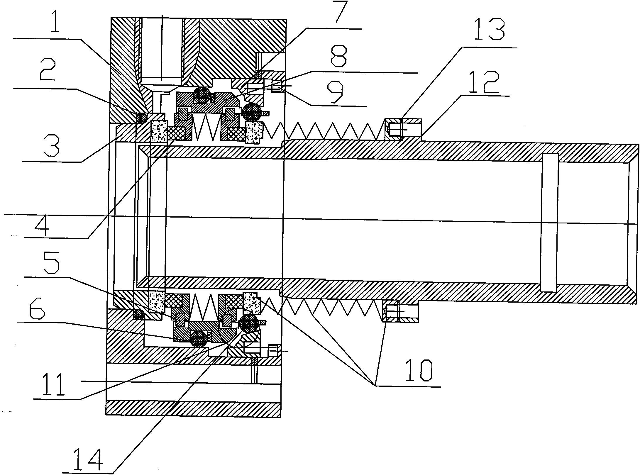
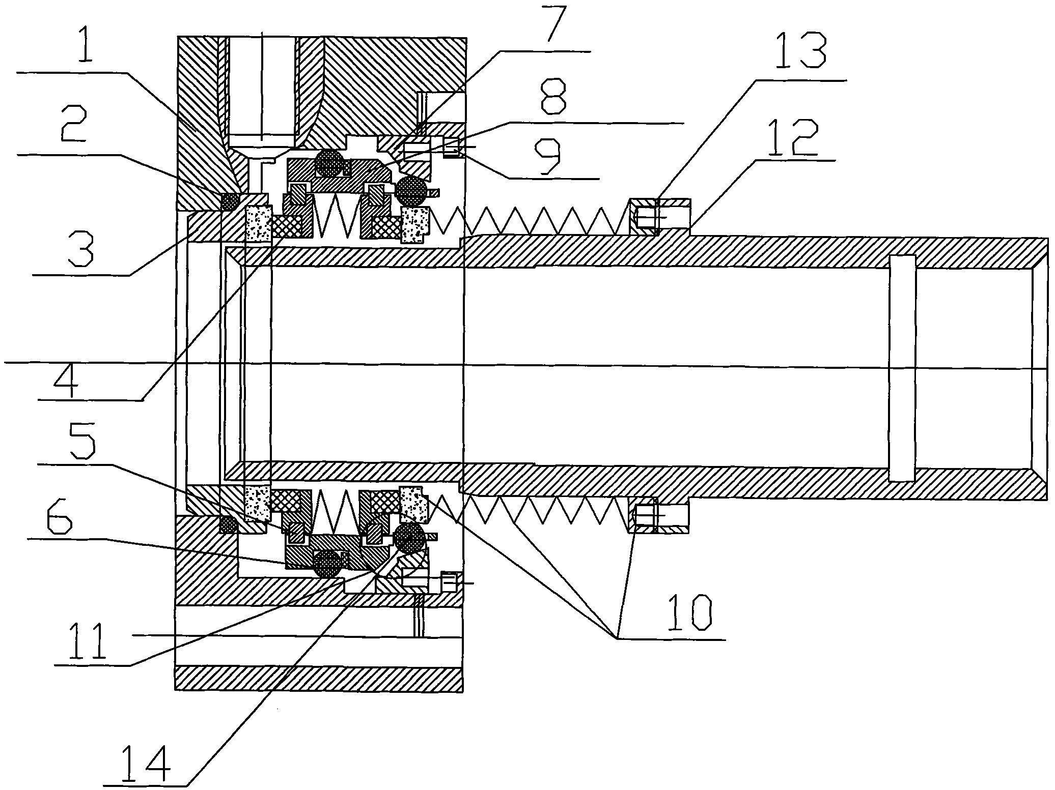
[0016] Such as figure 1 As shown, the bellows differential mechanical seal of the present invention includes a gland 1 and a shaft sleeve 12, and the gland 1 is equipped with a static ring 3, a bellows intermediate ring 4 and a differential shifting intermediate ring 8, and the gland 1 is provided with There is a gland 9, a bellows driving ring 10 is set on the shaft sleeve 12, a bellows differential assembly 11 is installed between the bellows intermediate ring 4 and the bellows driving ring 10, and the bellows differential assembly 11 A wedge ring 7 is installed inside, an O-ring 2 is set on the static ring 3, a differential ball 14 is installed between the wedge ring 7 and the bellows active ring 10, and between the gland 1 and the differential toggle intermediate ring 8 The ball 6 is installed, the bellows active ring 10 and the shaft sleeve 12 are connected with a gasket 13, the differential toggle intermediate ring 4 is equipped with a toggle pin 5, and the differential ...


PUM


Abstract

The invention discloses a corrugated pipe differential type mechanical seal comprising a press cover (1) and a shaft sleeve (12), wherein a static ring (3), a corrugated pipe intermediate ring (4) and a differential stirring intermediate ring (8) are arranged in the press cover (1), a corrugated pipe driving ring (10) is sleeved on the shaft sleeve (12), and a corrugated pipe differential mechanism assembly (11) is arranged between the corrugated pipe intermediate ring (4) and the corrugated pipe driving ring (10). The corrugated pipe differential type mechanical seal is provided with the differential stirring intermediate ring structure for match so that evacuation prevention, vibration prevention, following performance, differential performance, self-locking performance of degree of freedom, heat radiation performance and the pump conveyance performance of medium can be achieved in modes of simultaneous coexistence as well as coordinated and consistent running. The corrugated pipe differential type mechanical seal has the advantages of novel structure, good sealing performance and long service life.

Description

technical field [0001] The invention relates to a mechanical seal for a high-temperature pump and a kettle, in particular to a bellows differential mechanical seal. Background technique [0002] The problem of the actual service life of mechanical seals has always been the difficulty of pump dynamic seals in various industries in the world. At present, the general structure of mechanical seals is: the structure of static ring plus dynamic ring. , evacuation, cavitation, impurities, the characteristics of the medium, etc., resulting in large friction and wear of the mechanical seal, high friction heat, poor followability of the moving ring, and leakage of the shaft that often occurs in equipment and many other reasons. In addition, the original mechanical seal In terms of design, the original design life is 8000 hours / set (1 year), and its actual use side is shorter, which is far lower than the actual service life of the bearing. The advanced concept recognized internationall...

Claims


Application Information

Patent Timeline
Patent Type & Authority Applications(China)
IPC IPC(8): F16J15/52F16J15/18F16J15/16
Inventor 李世颖
Owner DALIAN JINFENG ACID RESISTING PUMP TECH
Learn More