Main runner structure of mould

A main channel and mold technology, applied in the field of injection mold structure, can solve the problems of waste of raw materials, increase of production cost, short service life of the mold, etc., and achieve the effect of no waste of raw materials, long service life and low production cost

Inactive Publication Date: 2011-01-19
VANGUARD TECH WUXI
View PDF4 Cites 3 Cited by
  • Summary
  • Abstract
  • Description
  • Claims
  • Application Information

AI Technical Summary

Problems solved by technology

[0002] When designing an injection mold, the sprue is generally located directly below the nozzle of the injection molding machine. Based on the design principle of the sprue that the length of the sprue should be as short as possible, the sprue is vertical to the cavity, but due to the influence of the product and the mold structure, Or due to the limitation of the gating system and the cavity, the sprue deviates from the center of the mold, and sometimes the distance of the deviation is still large, resulting in the following problems when the mold is used:
[0003] (1) When the product is ejected, because the center of gravity of the ejector is not at the center of the mold, the ejector plate and the bottom needle plate are in the process of ejection movement, causing the movement of the ejector pin and the slider to be unstable, and sometimes even causing the small ejector pin to break, resulting in The mold cannot be used normally, and the service life of the mold is short;
[0004] (2) Since the main channel is not in the center of the mold, it is easy to cause one side of the mold to be too large and cause overflow, wasting raw materials
[0005] In view of the above problems, it can be solved by using a three-plate mold structure, but this will make the mold structure complex and increase the production cost

Method used


Image

  • Main runner structure of mould
  • Main runner structure of mould

Examples


Embodiment Construction

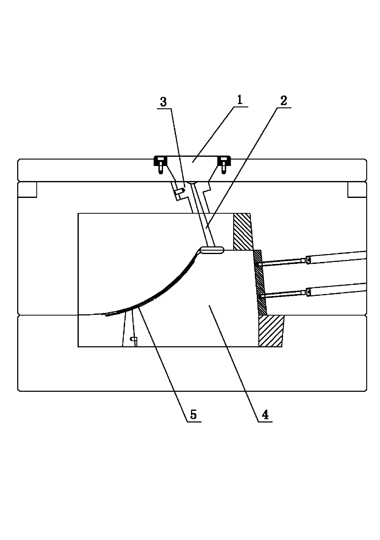
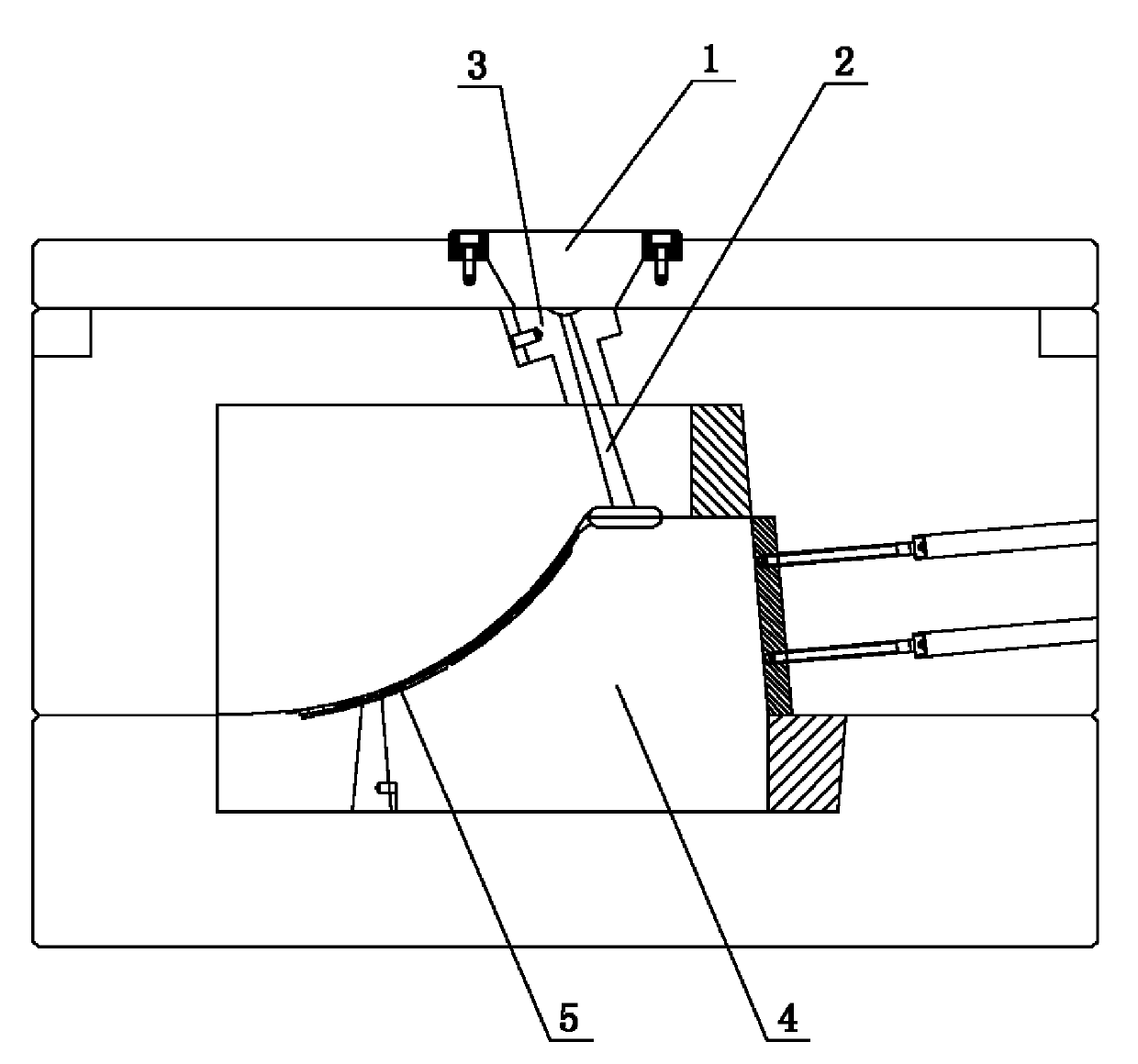
[0010] See figure 1 , the present invention includes injection molding machine nozzle 1, sprue 2, sprue sleeve 3, mold 4, mold cavity 5, nozzle 1 of injection molding machine is aligned with the top of sprue 2, sprue sleeve 3 is installed on the top of sprue 2 The outer edge, the bottom of the sprue 2 leads to the mold cavity 5, the sprue 2 is arranged obliquely, the outlet at the bottom of the sprue 2 is located in the center of the mold 4, the inner hole of the sprue sleeve 3 is arranged obliquely, and the inner hole of the sprue sleeve 3 The hole fits on the top outer edge of the sprue 2 .


PUM


Abstract

The invention provides a main runner structure of a mould, which enables the main runner of the mould to be positioned at the center of the mould. As a result, the service life of the mould is prolonged, no raw material is wasted in the process of injection molding and the manufacturing cost of the mould is low. The main runner structure comprises an injection molding machine nozzle, a main runner, a sprue bush, a mould and a mould cavity. The nozzle of the injection molding machine aligns with the top of the main runner, the sprue bush is arranged at the outer edge of the top of the main runner, and the bottom of the main runner leads to the mould cavity. The invention is characterized in that the main runner is obliquely arranged, a bottom outlet port of the main runner is positioned at the center of the mould, and the inner bores of the sprue bush are obliquely arranged and co-ordinately sleeved at the outer edge of the top of the main runner.

Description

technical field [0001] The invention relates to the structural field of injection molds, in particular to the main channel structure of the mold. Background technique [0002] When designing an injection mold, the sprue is generally located directly below the nozzle of the injection molding machine. Based on the design principle of the sprue that the length of the sprue should be as short as possible, the sprue is vertical to the cavity, but due to the influence of the product and the mold structure, Or due to the limitation of the gating system and the cavity, the sprue deviates from the center of the mold, and sometimes the distance of the deviation is still large, resulting in the following problems when the mold is used: [0003] (1) When the product is ejected, because the center of gravity of the ejector is not at the center of the mold, the ejector plate and the bottom needle plate are in the process of ejection movement, causing the movement of the ejector pin and th...

Claims


Application Information

Patent Timeline
Patent Type & Authority Applications(China)
IPC IPC(8): B29C45/27
Inventor 张卫
Owner VANGUARD TECH WUXI
Why Eureka
Try Eureka