Heat exchange device and thermal management system

A technology of heat exchange device and heat management system, applied in heat storage equipment, indirect heat exchanger, transportation and packaging, etc., can solve the problem of sensible heat reducing heat energy storage capacity and so on

Active Publication Date: 2011-01-19
VALEO SYST THERMIQUES
View PDF5 Cites 18 Cited by
  • Summary
  • Abstract
  • Description
  • Claims
  • Application Information

AI Technical Summary

Problems solved by technology

[0019] Utilization of sensible heat significantly reduces thermal energy storage capacity

Method used


Image

  • Heat exchange device and thermal management system
  • Heat exchange device and thermal management system

Examples


Embodiment Construction

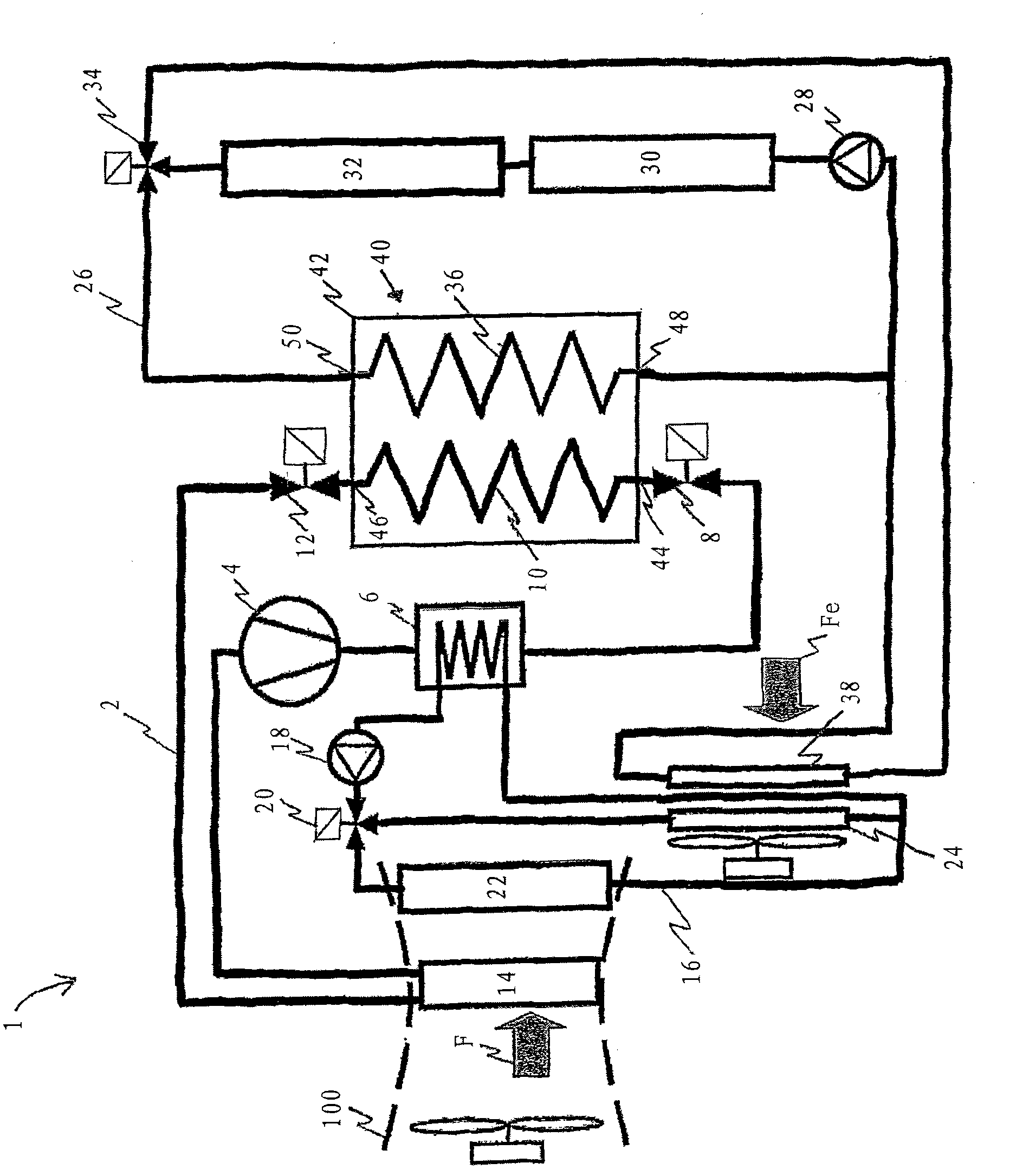
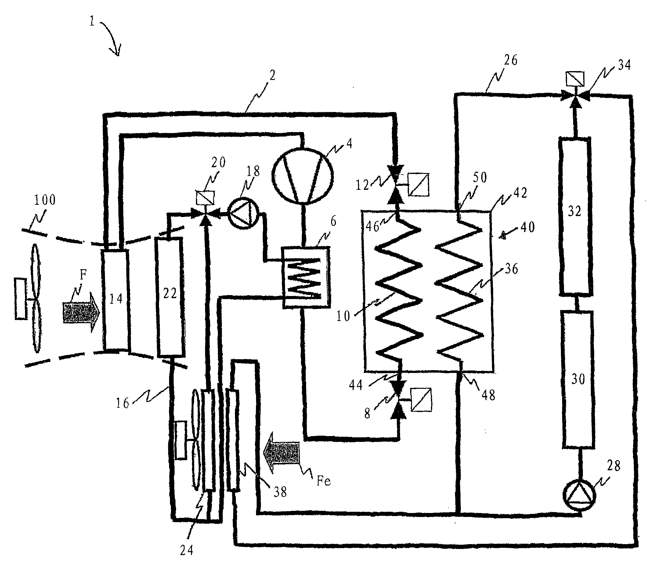
[0048] figure 1 A first embodiment mode of the present invention is shown. The thermal management system 1 comprises an air conditioning loop 2 , a primary loop 16 and a secondary loop 26 . The thermal management system 1 of a car allows regulating the temperature of car components such as the car battery pack, while allowing thermal comfort for the car's occupants through ventilation, heating and / or air conditioning equipment 100 .

[0049] The air conditioning loop 2 in which the refrigerant fluid circulates includes a compressor 4, a refrigerant-heat carrier heat exchanger 6, a first pressure reducing device 8, a first heat exchanger 10, a second pressure reducing device 12 and Evaporator 14. The refrigerant fluid is R134a, R744 (CO 2 ) or R1234yf. In the following description, the cooling fluid is referred to as "refrigerant". The evaporator 14 is located inside the ventilation, heating and / or air-conditioning device 100, in which the primary air flow F circulates in ...


PUM


Abstract

The invention relates to a heat exchange device and a thermal management system. The device (40) is equipped in a thermal management system and includes a first heat exchanger (10) allowing a cooling fluid to pass, a second heat exchanger (36) allowing carried hot fluid to pass. The device (40) includes a heat storing member (M) for heat exchange with first and second heat exchangers (10, 36). The thermal management system (1) includes such a heat exchange device (40).

Description

technical field [0001] The invention relates to the technical field of thermal management systems for automobiles. More specifically, the invention aims at providing a thermal management system comprising an air conditioning circuit for ventilation, heating and / or air conditioning equipment. Background technique [0002] As is known, automobiles are equipped with ventilation, heating and / or air conditioning equipment in order to thermally treat the air in the cabin. [0003] This equipment includes an air conditioning circuit that ensures that the air passing through the ventilation, heating and / or air conditioning equipment is cooled and dehumidified before being introduced into the cabin. This cooling and dehumidification is accomplished by circulating a refrigerant fluid through the evaporator with a compressor connected to the vehicle's heat engine. It also includes a heating circuit that ensures that the air passing through the ventilation, heating and / or air conditio...

Claims


Application Information

Patent Timeline
Patent Type & Authority Applications(China)
IPC IPC(8): F28D20/00F28D20/02B60H1/00
CPCB60H2001/00928B60H1/00492B60H1/32281
Inventor 斯蒂芬·卡尔
Owner VALEO SYST THERMIQUES
Why Eureka
Try Eureka