
Finger mechanism of robot hand

A technology of robotic hands and fingers, applied in the field of improving technology

Inactive Publication Date: 2011-01-19
HARMONIC DRIVE SYST IND CO LTD
View PDF2 Cites 4 Cited by
  • Summary
  • Abstract
  • Description
  • Claims
  • Application Information

AI Technical Summary

Problems solved by technology

In the finger mechanism of the robotic hand disclosed in the above-mentioned patent documents, in general, compared with the force required to drive the fingers toward the gripping object, the force used to drive the fingers toward the opening direction can be small, There is a large difference between the force required depending on the driving direction

Method used


Image

  • Finger mechanism of robot hand
  • Finger mechanism of robot hand
  • Finger mechanism of robot hand

Examples


Embodiment Construction

[0044] Hereinafter, embodiments of a finger mechanism of a robot hand to which the present invention is applied will be described with reference to the drawings.

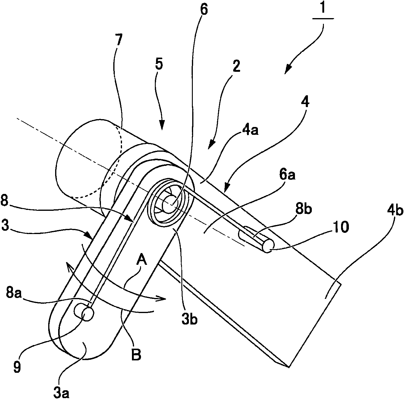
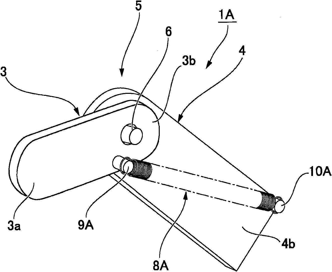
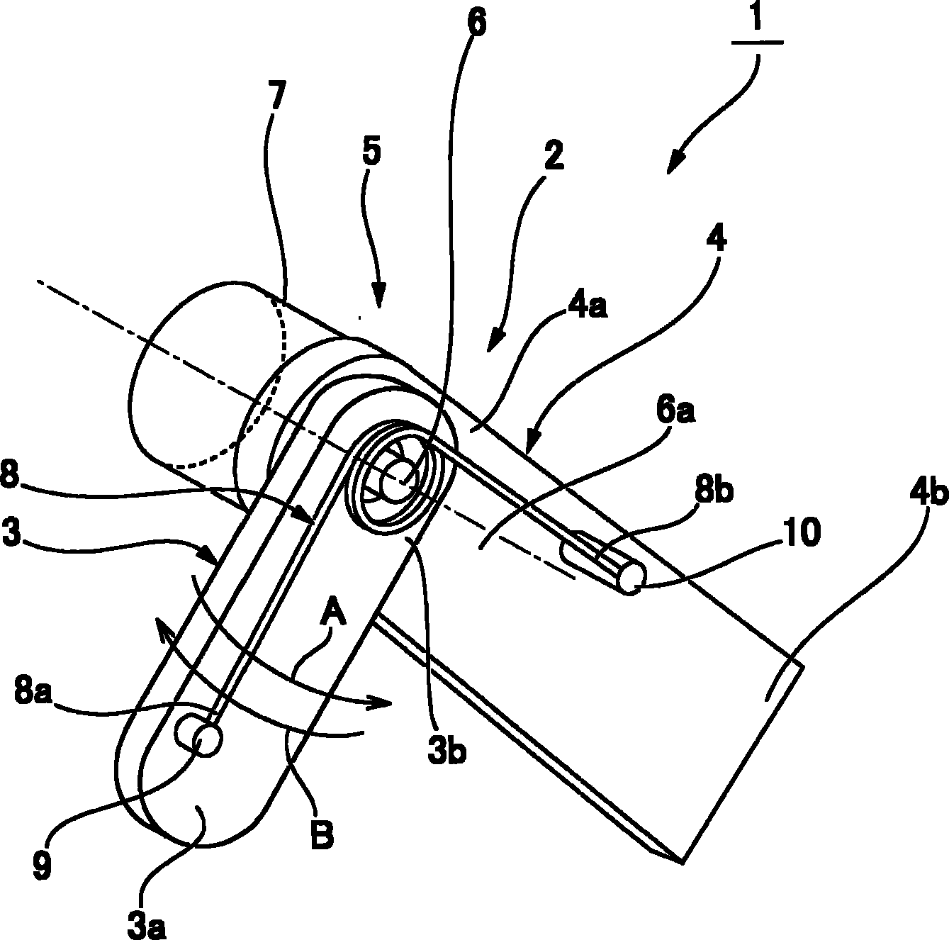
[0045] figure 1 It is an explanatory diagram showing main parts of the finger mechanism of the robot hand according to the present embodiment. The finger mechanism 1 of the robotic hand includes one or more fingers or finger units 2, and only one finger unit is shown in the figure. The finger unit 2 includes a tip-side finger link 3 , a base-side finger link 4 , and a finger joint 5 connecting the tip-side finger link 3 and the base-side finger link 4 .

[0046] The front finger link 3 is formed of, for example, an elongated plate member, and its rear end 3 b is connected and fixed to the finger joint in a state where the front finger link 3 extends in a direction perpendicular to the central axis 6 a of the finger joint shaft 6 . 5 for finger joint axis 6 . When the finger joint shaft 6 rotates, the front finger...


PUM


Abstract

A finger unit (2) of a finger mechanism (1) of a robot hand comprises a tip-side finger link (3), a root-side finger link (4), and a finger joint portion (5) for connecting the tip-side finger link (3) and the root-side finger link (4). The tip-side finger link (3) is constantly applied with torque in the robot hand gripping direction (A) around a finger joint shaft (6) by a torsion coil spring (8), reducing output torque of an electromagnetic motor (7) necessary for driving the finger mechanism (1) in the gripping direction (A). Due to this structure, the finger mechanism of the robot hand which can provide necessary driving force in the robot hand gripping direction using a low-output and compact actuator can be realized.

Description

technical field [0001] The present invention relates to a finger mechanism of a robotic hand, in particular, to an improved technology for realizing miniaturization and cost reduction of the finger mechanism. Background technique [0002] The applicant of the present application has proposed devices disclosed in Patent Documents 1 and 2 as a robot hand for grasping and manipulating objects. In the finger mechanism of the robotic hand disclosed in the above-mentioned patent documents, in general, compared with the force required to drive the fingers toward the gripping object, the force used to drive the fingers toward the opening direction can be small, There is a large difference between the required forces depending on the driving direction. However, the electromagnetic motors used for the drive of the finger joints of the robotic hand do not differentiate the direction of rotation, but generate the same torque. Therefore, in the finger mechanism of the robotic hand, it ...

Claims


Application Information

Patent Timeline
IPC IPC(8): B25J15/08
CPCB25J15/0009Y10T74/20317
Inventor 金山尚树
Owner HARMONIC DRIVE SYST IND CO LTD
Learn More