
Transversal bumper support for motor vehicles

A technology for bumpers and motor vehicles, applied in the direction of bumpers, etc., can solve problems such as damage, and achieve the effect of increasing the overlapping area and saving weight

Inactive Publication Date: 2011-01-19
派格有限公司
View PDF4 Cites 3 Cited by
  • Summary
  • Abstract
  • Description
  • Claims
  • Application Information

AI Technical Summary

Problems solved by technology

The bumper cross member is offset forward in the longitudinal direction in its central region, so that although the motor vehicles involved in the accident have different structural heights and in the event of a collision, overrunning or underrunning of the bumper system is also possible. Reduced damage, but significant damage is still always to be expected in this case

Method used


Image

  • Transversal bumper support for motor vehicles
  • Transversal bumper support for motor vehicles
  • Transversal bumper support for motor vehicles

Examples


Embodiment Construction

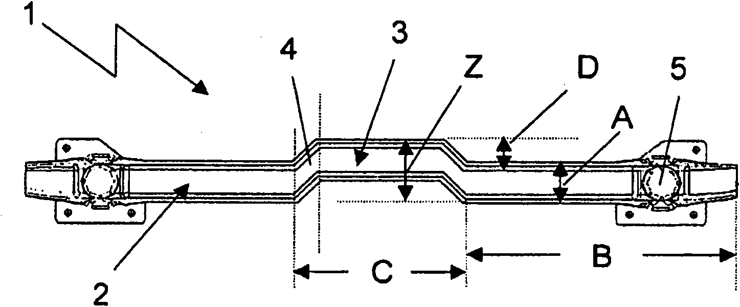
[0027] figure 1 For comparison, a conventional bumper beam 1 is shown in front view, which is of rectilinear design with a constant cross-sectional height (A) over its entire length. Fastening devices 5 can be seen in the lateral sections, via which the bumper cross member is connected to the longitudinal members of the bodywork.

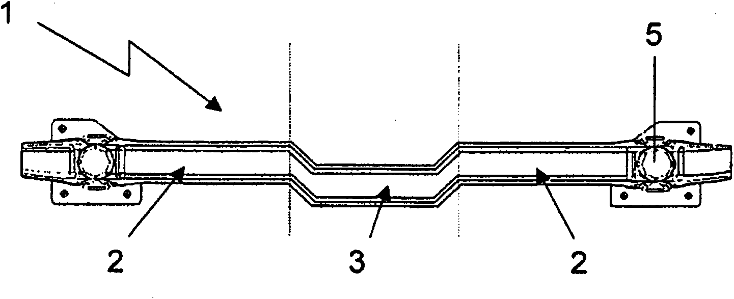
[0028] figure 2A bumper beam 1 according to the invention is likewise shown in front view. The bumper beam 1 has a substantially constant cross-sectional height (A) over its length and is substantially composed of a total of three subregions 2 , 3 consisting of two identical outer parts 2 and a different outer part The middle part of 2 consists of 3. The central part 3 is offset vertically upwards relative to the respective outer part 2 , wherein the vertical offset dimension (D) in the present case is approximately equal to the cross-sectional height (A) of the bumper crossbeam 1 . By vertically offsetting the dimension (D), the overlapping ar...


PUM


Abstract

The present invention relates to a transversal bumper support 1, comprising a plurality of partial regions, with an increased height Z in the Z-direction due to a vertical displacement of the middle partial region 3 of the transversal bumper support 1.

Description

technical field [0001] The invention relates to a bumper beam for the front and / or rear region of a motor vehicle having the features of the preamble of claim 1 . Background technique [0002] In order to be able to absorb the forces acting when two motor vehicles collide to a sufficient extent without having to endure, for example, significant deformations of the passenger compartment, a Bumper systems and these are connected to the side members in order to transmit forces via the bumpers into the side members. Since the height of motor vehicles changes considerably today even in passenger cars, it can be the case when two motor vehicles collide that the bumpers of the two vehicles do not collide and therefore it is not possible to apply the forces optimally. into each stringer. This can lead to significant damage to the passenger compartment or other functional components in the front or rear area of ​​the vehicle. As a result, not only are the occupants exposed to dang...

Claims


Application Information

Patent Timeline
Patent Type & Authority Applications(China)
IPC IPC(8): B60R19/04
CPCB60R19/04B60R19/34
Inventor M·勒夫勒
Owner 派格有限公司
Learn More