
Biometric authentication apparatus

A technology of biometric authentication and microlens array, which is applied in the field of biometric authentication devices and can solve problems such as deterioration of authentication accuracy

Inactive Publication Date: 2013-07-10
SONY GRP CORP
View PDF1 Cites 0 Cited by
  • Summary
  • Abstract
  • Description
  • Claims
  • Application Information

AI Technical Summary

Problems solved by technology

There was a problem that authentication accuracy deteriorated due to the influence of external light

Method used


Image

  • Biometric authentication apparatus
  • Biometric authentication apparatus
  • Biometric authentication apparatus

Examples


Embodiment Construction

[0020] Embodiments of the present invention will be described in detail below with reference to the accompanying drawings in the following order.

[0021] (1) Overall configuration

[0022] (2) Assembly method

[0023] (1) Overall configuration

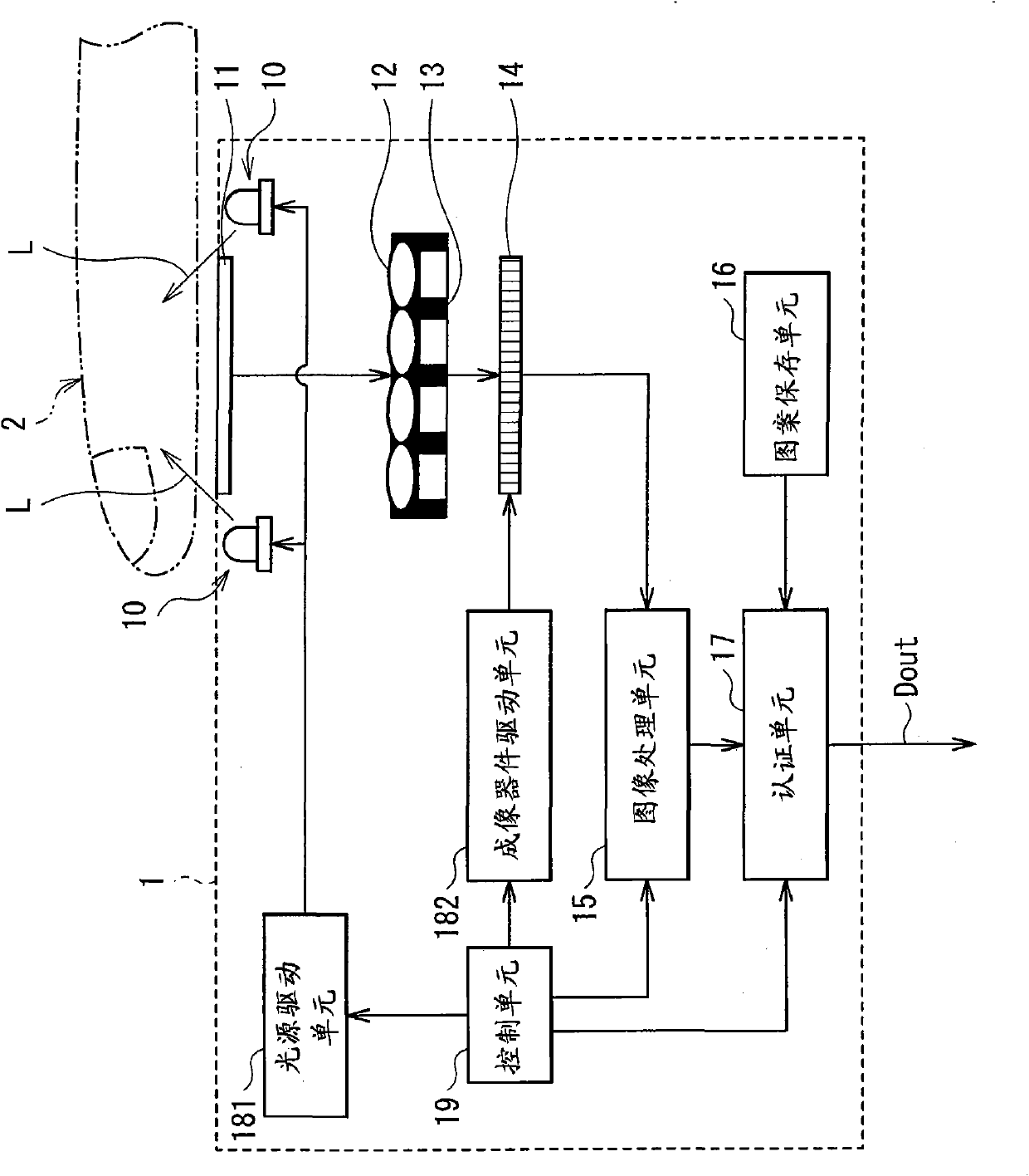
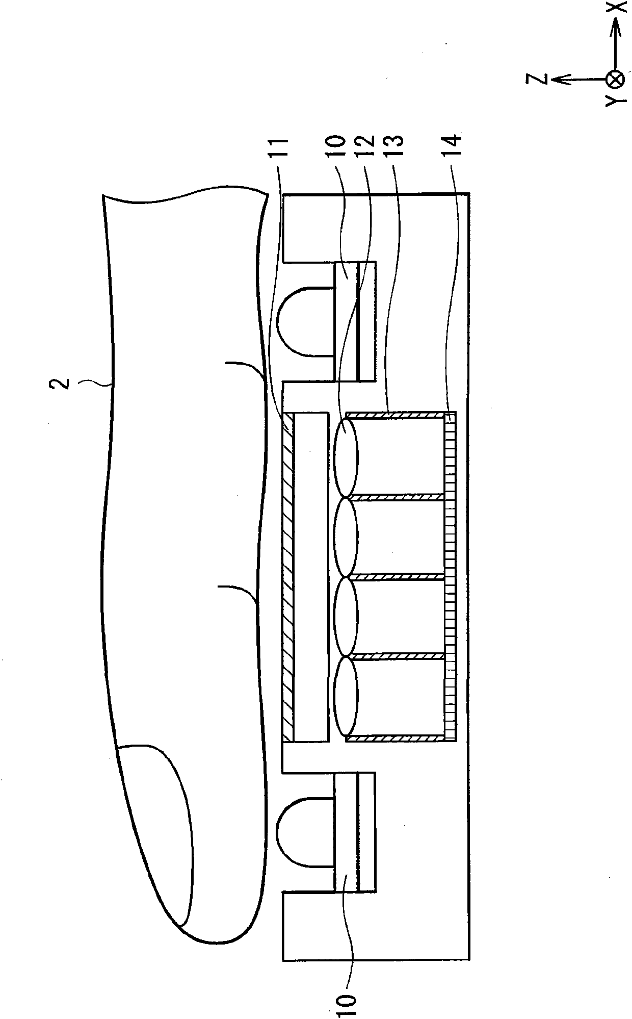
[0024] figure 1 The overall configuration of the biometric authentication device 1 according to the embodiment of the present invention is shown. figure 2 A Z-X cross-sectional configuration of the biometric authentication device 1 is shown. The biometric authentication device 1 takes an image of, in particular, a structure of a living body (for example, a fingertip) 2 such as a vein and performs authentication. The biometric authentication device 1 has a light source 10, an inspection unit 11, a microlens array 12, a light shielding unit 13, an imaging device 14, an image processing unit 15, a pattern saving unit 16, an authentication unit 17, a light source driving unit 181, an imaging device driving unit 182 and control unit ...


PUM


Abstract

The present application describes a biometric authentication apparatus realizing reduction in thickness while holding high authentication precision. The biometrics authentication apparatus includes: a light source emitting light in a wavelength range including a wavelength range for authentication toward a living body; a microlens array condensing light from the living body and selectively transmitting light in the wavelength range for authentication; an imaging device obtaining image data of the living body on the basis of the light condensed by the microlens array; and an authentication unit authenticating the living body on the basis of the image data obtained by the imaging device.

Description

technical field [0001] The present invention relates to a biometric authentication device for authenticating a living body based on data obtained by imaging a structure in a biological part such as a vein or a fingerprint. Background technique [0002] In the related art, imaging devices for imaging structures in biological parts are used for biometric authentication devices and the like, and various authentication devices for authenticating living bodies using image data such as fingerprints or veins are proposed. Generally, in this biometric authentication device, since the imaging device itself is thick, in order to apply the device to a thin device, a method of arranging the imaging device outside the authentication device or an optical system of the imaging device independently of each other is mainly used. (imaging lens) and detection system (imaging device) method. [0003] However, in recent years, as various devices have become thinner or due to manufacturability o...

Claims


Application Information

Patent Timeline
Patent Type & Authority Patents(China)
IPC IPC(8): A61B5/117G06K9/00H04N23/40
CPCG06K2009/0006G06K9/0004G06K2009/00932H01L27/14627G06V40/1341G06V40/1318G06V40/14
Inventor 市村功甲斐慎一渡边俊夫川岛良成
Owner SONY GRP CORP
Learn More