Photovoltaic-photothermal device

A photovoltaic and photothermal technology, applied in photovoltaic thermoelectric hybrid power generation, photovoltaic modules, photovoltaic power generation, etc., can solve the problems of energy waste, high solar energy loss, and low photoelectric conversion efficiency, so as to increase the sunlight receiving area and overcome the insufficiency of use frequency High, overcoming the effect of low conversion efficiency

Pending Publication Date: 2020-07-10
SHANGHAI XINGYE MATERIALS TECH CO LTD
View PDF0 Cites 5 Cited by
  • Summary
  • Abstract
  • Description
  • Claims
  • Application Information

AI Technical Summary

Problems solved by technology

The solar power generation device and the heating device in the prior art are two separate devices. Since the photovoltaic utilization and photothermal utilization of solar energy have their own advantages and disadvantages, there is a problem that they cannot be installed at the same time, that is, they can only generate electricity but not heat or only It can heat but not generate electricity, so that the two cannot complement each other, and cannot perform heating and power generation at the same time, which affects the full and efficient use of solar energy
[0003] When purely photovoltaic power generation, the photoelectric conversion efficiency is low, and its conversion efficiency is generally 12%-17% of the solar radiation, that is to say, about 83% of the solar energy irradiated on the surface of the photovoltaic panel cannot be utilized and converted, and a considerable part of the energy It is converted into heat energy loss, and the heat energy generated will also increase the temperature of the photovoltaic panel, resulting in a decrease in battery efficiency and further reducing the photoelectric conversion rate; therefore, pure photovoltaic power generation has the problems of low conversion rate and high solar energy loss
[0004] In the case of pure photothermal heating, such as common solar water heaters, the photothermal conversion efficiency is high, generally more than 50% of the solar radiation. The hot water is put on hold and wasted, especially for schools equipped with solar water heating systems. In the first semester, solar hot water can meet the needs of students. In addition, for the solar hot water heating system, the efficiency of solar thermal heating equipment is much higher than that of photovoltaic power generation heating equipment, such as heating a 100 square meter house in winter, such as Installing a photovoltaic power generation device of 50 square meters, the power generated in sunny days cannot meet the requirements. For example, installing a photothermal utilization device of 50 square meters and heating with hot water can fully absorb the heat energy required. However, houses are generally only heated in winter. , the heating time is about three months, and most of the rest of the time is in a state of shelving. The collected heat energy is useless and wasted;
[0005] To sum up, at present, the above-mentioned problems in the two utilization methods of photovoltaic power generation and photothermal heating of solar energy lead to insufficient utilization of solar energy, and products based on solar energy have not yet been popularized or applied on a large scale in the market. The unique attributes of cleanliness, availability, and inexhaustibility have not been well developed and utilized. Due to the lack of people's application and research and development of solar energy technology, the shortcomings of products using solar energy technology have become more prominent and more serious. Yes, even similar products such as solar water heaters have been abandoned in the market. Therefore, in the face of the current energy crisis and the pursuit of cleanliness and pollution-free, there is an urgent need for innovation in the utilization of solar energy
[0006] However, in practice, the combination of photovoltaic power generation and solar thermal heating has always been a difficult technical problem to overcome. There are many technical problems to be overcome in the combination of the two, which is also determined by the current basic equipment of photovoltaic power generation and solar thermal heating. Pros: Because most of the photovoltaic panels are flat and complete panels, and most of the photothermal equipment are arranged heat collector tubes, so that the photovoltaic panels and heat collector tubes cannot be combined and work together to make up for the respective shortcomings of the two technologies and maximize the use of solar energy. To obtain two types of income, hot water and electricity. At present, there are very few devices on the market that combine photovoltaic power generation and solar thermal heating to simultaneously produce thermal energy and electricity. Some existing devices are installed on the back of the photovoltaic panel to use heat with heat collectors. However, the problem with this method is that the heat collected by the heat collector will still cause the heat to not be dissipated, and the temperature of the photovoltaic panel will also increase, resulting in a decrease in battery efficiency and shortened service life; therefore, a photovoltaic- The photovoltaic-photothermal device with photothermal switching is of great significance, and it has innovative significance for the full utilization of solar energy and the application of products to family life

Method used


Image

  • Photovoltaic-photothermal device
  • Photovoltaic-photothermal device
  • Photovoltaic-photothermal device

Examples


Embodiment 1

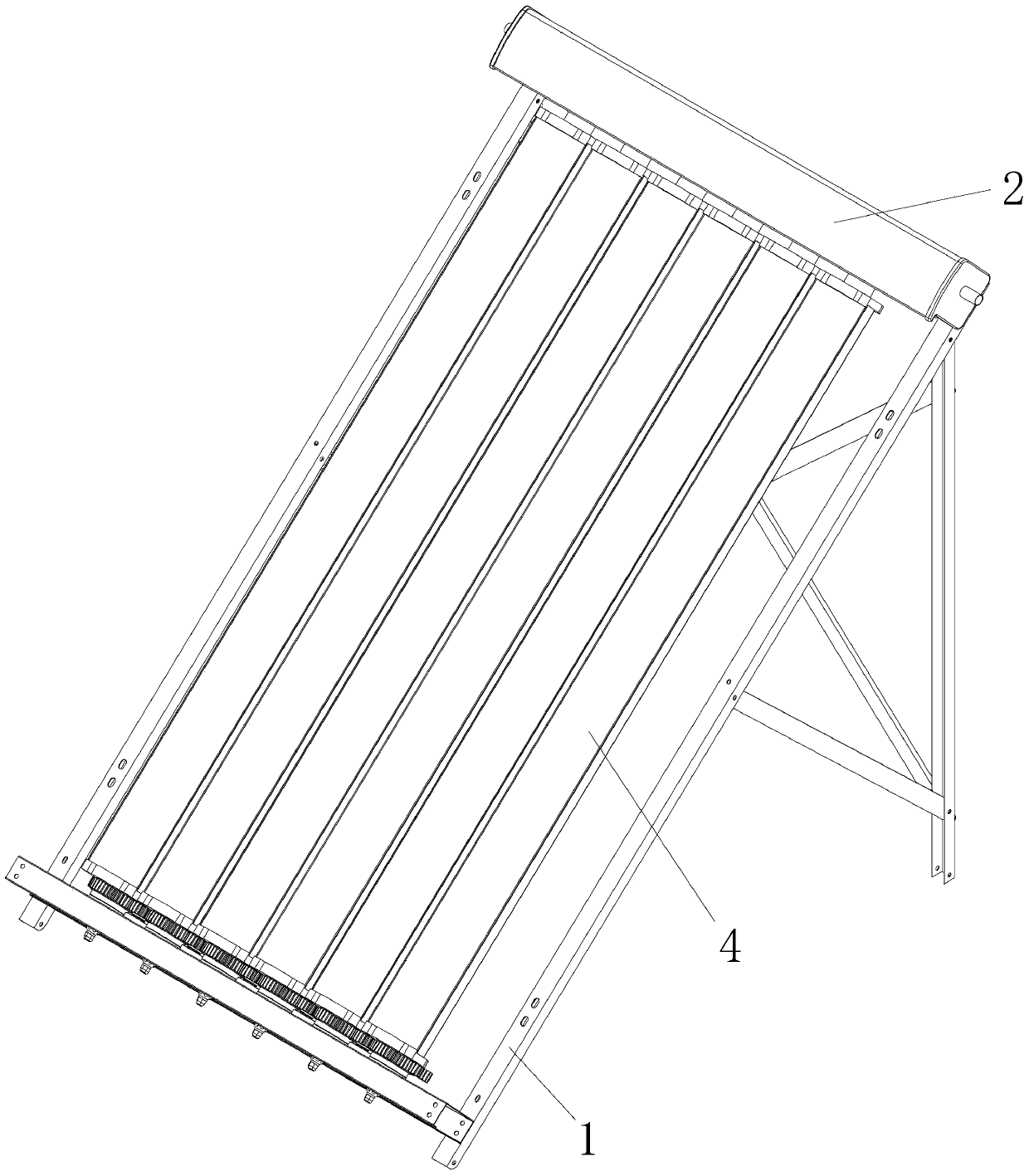
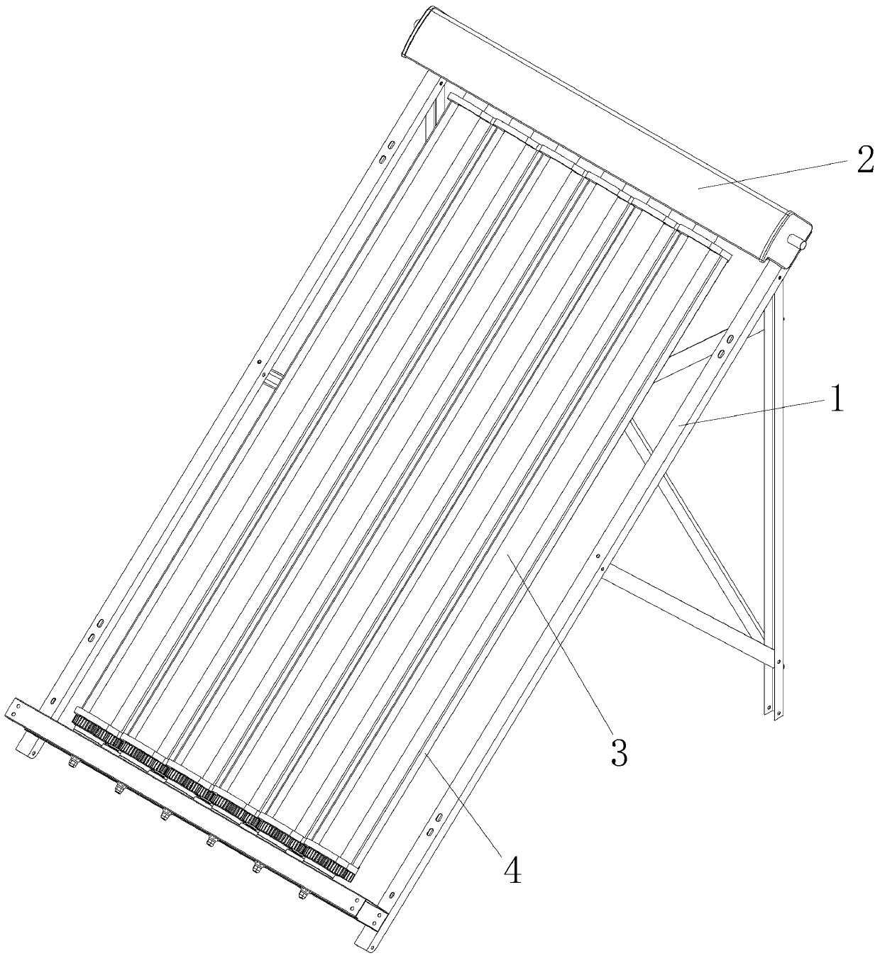
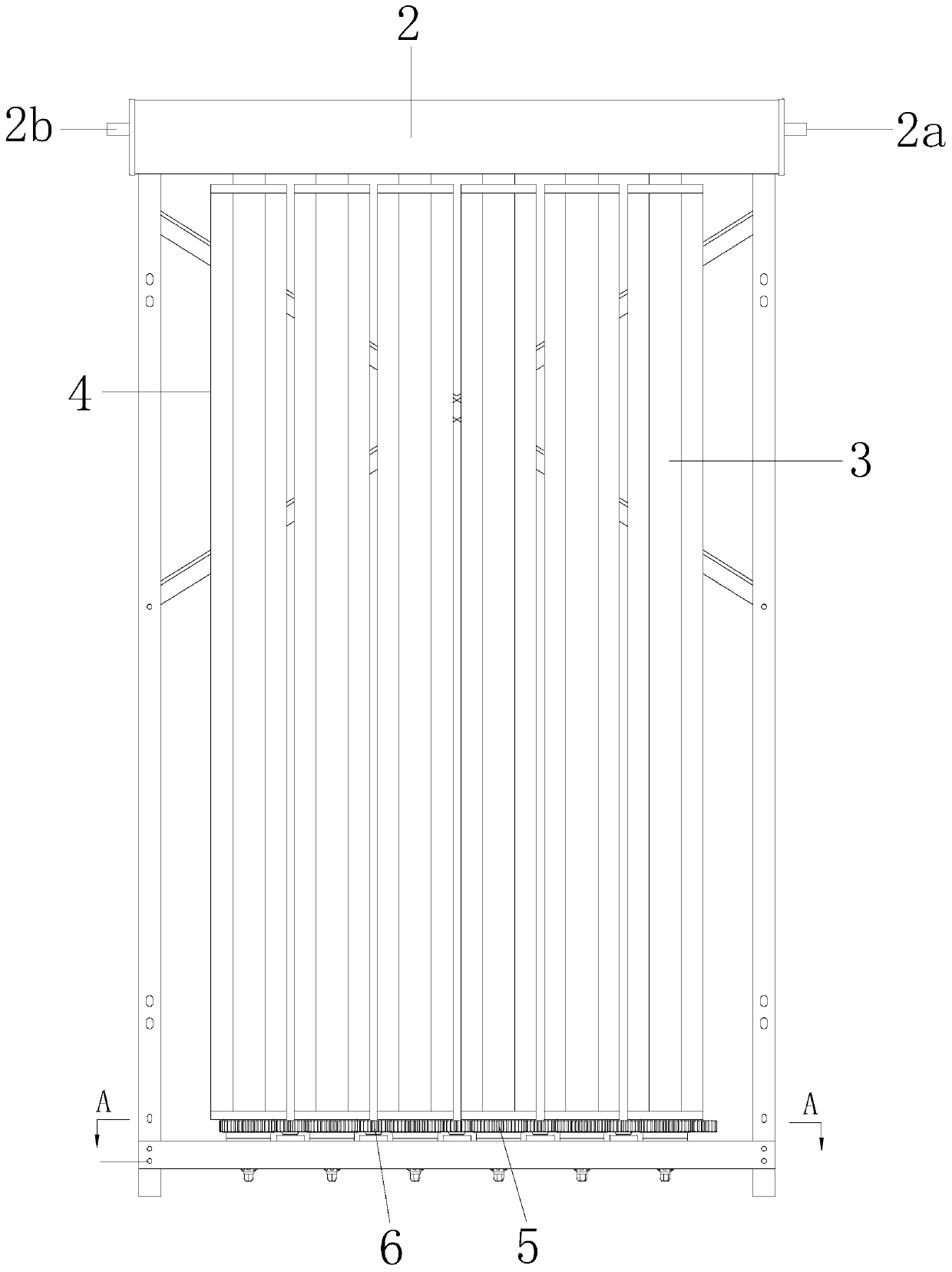
[0072] Figure 1 to Figure 5 A preferred embodiment of the photovoltaic-photothermal device of the present application is shown. Same as some existing photothermal devices (such as solar water heaters), the photovoltaic-photothermal device of this embodiment also includes a base frame 1 on which a water tank 2 and six heat collecting tubes 3 are fixedly arranged. The water tank 2 has a water inlet port 2a and a water outlet port 2b. During actual application, the aforementioned water inlet port 2a and the water outlet port 2b are connected to the water inlet pipeline and the water outlet pipeline respectively, so as to feed the water tank 2 into flowing water. One end of aforementioned each heat collecting tube 3 is all inserted in the water tank (fitting place is sealed and watertight). For the convenience of manufacture and assembly, the aforementioned heat collecting tubes 3 are arranged in the same plane at equal intervals. The base frame 1 is used as the supporting carr...

Embodiment 2

[0094] Image 6 with Figure 7 The second preferred embodiment of the photovoltaic-photothermal device of the present application is shown. The structure of the photovoltaic-photothermal device of this embodiment is basically the same as that of the first embodiment, the only difference being that the heat collecting tube 3 is connected in rotation (and The fastening connection in non-embodiment 1) is on the base frame 1, and the photovoltaic panel 4 and the heat collecting tube 3 in the same photovoltaic-photothermal unit are fixedly connected to each other through the connecting frame 9. When the photovoltaic panel 4 rotates on the base frame 1, the heat collecting tube 3 fixed with the photovoltaic panel 4 also rotates thereupon. Naturally, when the heat collecting tube 3 rotated on the base frame 1, the photovoltaic panel 4 fixed with the heat collecting tube 3 also rotated with the heat collecting tube 3.

[0095] The rotating connection structure between the heat colle...

Embodiment 3

[0105] Figure 8 It shows the third preferred embodiment of the photovoltaic-photothermal device of the present application. The structure of the photovoltaic-photothermal device of this embodiment is also basically the same as that of the first embodiment. The only difference is that the photovoltaic panel of this embodiment is 4. A reflector 8 is fixedly connected to the side facing the heat collecting tube 3, and the reflector 8 has a reflective surface facing the heat collecting tube 3.

[0106] When the photovoltaic-photothermal device is in the photothermal working mode, the photovoltaic panel 4 and the reflector 8 fixed on the photovoltaic panel are turned to the backlight side of the heat collecting tube 3, and at this time, the reflective surface of the reflector 8 faces the sunlight, and the reflector 8 from the collector The sunlight incident on the side of the heat pipe 3 will shoot to the reflective surface of the reflector 8, and after being reflected by the refl...


PUM


Abstract

The invention relates to a photovoltaic-photothermal device. The photovoltaic-photothermal device comprises a bed frame, a water passing box fixed to the bed frame and heat collection pipes connectedwith the bed frame. Each heat collection pipe comprises a vacuum pipe body formed by an inner pipe and an outer pipe which are coaxially fixed, a heat absorption coating arranged on the pipe wall of the inner pipe in a coating manner, a heat conduction rod movably arranged in the inner pipe and connected with the inner pipe and aluminum foil. Each heat conduction rod comprises a heat conduction rod stretching-out end which stretches out of the corresponding inner pipe and is inserted into the water passing box. The heat conduction rod stretching-out ends are sealed and fixedly inserted into the water passing box. The vacuum pipe bodies are rotationally connected with the bed frame. Photovoltaic plates rotating along with the vacuum pipe bodies are fixedly connected to the radial outer sides of the vacuum pipe bodies. The photovoltaic plates are provided with photovoltaic work faces deviating from the heat collection pipes. By means of the device, photovoltaic power generation and photothermal heating are combined, the photovoltaic or photothermal work mode can be selected according to needs, and the utilization rate to solar energy can be improved.

Description

technical field [0001] This application relates to photovoltaic-photothermal devices, especially photovoltaic-photothermal devices that can realize photovoltaic-photothermal switching. Background technique [0002] Solar energy, as a renewable energy source, has been widely used, such as photovoltaic power generation, solar thermal heating, solar thermal power generation, etc. Solar energy is also the main direction for the development of green energy in the future. There are currently two technical approaches for utilizing solar energy: the technical products of photovoltaic power generation and photothermal heating have been popularized in every country in the world. The solar power generation device and the heating device in the prior art are two separate devices. Since the photovoltaic utilization and photothermal utilization of solar energy have their own advantages and disadvantages, there is a problem that they cannot be installed at the same time, that is, they can o...

Claims


Application Information

Patent Timeline
Patent Type & Authority Applications(China)
IPC IPC(8): F24S10/40F24S10/70F24S10/95F24S30/40F24S23/70F24S70/20F24S50/20H02S40/44H02S20/32
CPCF24S10/40F24S10/70F24S10/95F24S23/70F24S30/40F24S50/20F24S70/20H02S20/32H02S40/44Y02E10/44Y02E10/47Y02E10/50Y02E10/60
Inventor 高峰刘在祥陈艳红朱涛蔡园丰王兵牛争艳
Owner SHANGHAI XINGYE MATERIALS TECH CO LTD
Why Eureka
Try Eureka