Electrolysis bath electrode

An electrolytic cell and electrode technology, applied in the direction of electrode shape/type, can solve the problems of low electrolysis efficiency, large space occupation, and large energy dissipation of electrolytic cell plate-shaped electrodes, so as to improve electrolysis efficiency and reduce energy dissipation. Effect

Inactive Publication Date: 2011-01-26
褚礼政
View PDF0 Cites 2 Cited by
  • Summary
  • Abstract
  • Description
  • Claims
  • Application Information

AI Technical Summary

Problems solved by technology

However, for the current planar electrode, it takes up a lot of space. In addition, the electric field it generates is a uniform electric field. The uniform electric field is distributed in the entire container tank, and its energy dispersion is high. The area near the electrode, therefore, the current plate electrode of the electrolyzer has a large energy dissipation and low electrolysis efficiency

Method used


Image

  • Electrolysis bath electrode
  • Electrolysis bath electrode

Examples


Embodiment Construction

[0008] Below in conjunction with accompanying drawing and embodiment the present invention is further described:

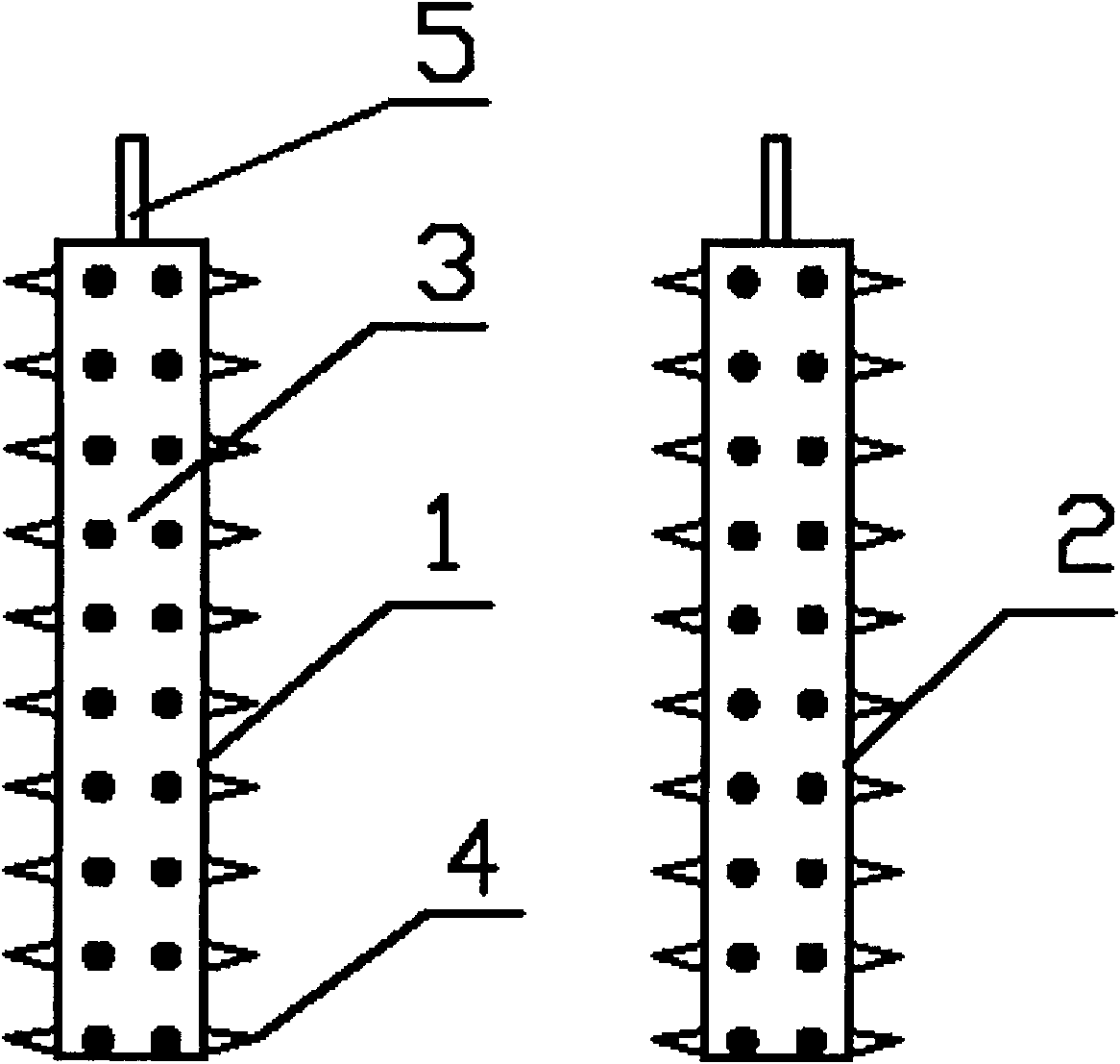
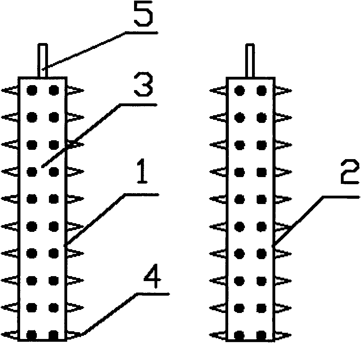
[0009] In the embodiment shown in the drawings, the electrolytic cell electrodes include a positive electrode 1 and a negative electrode 2, and the positive electrode 1 and the negative electrode 2 have the same shape and structure, and all include an electrode joint 5, a conductor column 3, and a conductor cone. 4. The conductor column 3 is a cylindrical conductor whose surface is evenly covered with the conductor cone 4, the conductor cone 4 is a conical conductor, the electrode joint 5 is above the conductor column 3, and The external DC power supply is connected, and the positive electrode 1 and the negative electrode 2 are arranged in the electrolytic solution in the electrolytic cell with an appropriate distance.

[0010] For the above-mentioned electrolytic cell electrodes, the materials of the conductor column 3 and the conductor cone 4 of the positive ele...


PUM


Abstract

The invention provides an electrolysis bath electrode, which comprises a positive electrode and a negative electrode, wherein the positive electrode and the negative electrode have same shapes and structures, and both the positive electrode and the negative electrode comprise an electrode contact, a conductor column and conductor cones; the conductor column is a section of cylindrical conductor, the conductor cones are uniformly distributed on the surface of the conductor column; the conductor cones are cone conductors; the electrode contact is arranged above the conductor column and is connected with an external direct current power supply; and the positive electrode and the positive electrode are arranged in electrolytic solution in an electrolysis bath at a certain distance from each other. The electrolysis bath electrode not only can effectively electrolyze solution to prepare required industrial materials, but also optimize the electric field distribution in the electrolysis bath, reduces the energy dissipation of the electrolysis bath, and improves the electrolytic efficiency of the electrolysis bath.

Description

Technical field [0001] The invention relates to the field of chemical industry, in particular to an electrode of an electrolytic cell. Background technique [0002] At present, in the field of chemical industry, electrolytic cells are often used to decompose solutions. The general working process of electrolytic cells is as follows: put an appropriate amount of original solution in the container tank, such as NaCl solution, and NaCl is free in the solution. + ions and Cl - ions, an anode chamber and a cathode chamber are set in the container tank, an anode plate is placed in the anode chamber, and a cathode plate is placed in the cathode chamber. A constant electric field is generated between them, which promotes the cations to move to the cathode plate, and the anions to move to the anode plate, so that the anions and cations in the original solution are separated, and each of them undergoes oxidation or reduction reaction on the corresponding plate side to generate the de...

Claims


Application Information

Patent Timeline
Patent Type & Authority Applications(China)
IPC IPC(8): C25B11/02
Inventor 褚礼政
Owner 褚礼政
Why Eureka
Try Eureka