
Steel bar arrangement method and steel bar arrangement device for reinforced concrete deep beam

A reinforced concrete and concrete technology, applied in the direction of joists, girders, trusses, etc., can solve the problems of weakened bonding performance between concrete and steel plates, complicated production methods, and falling off of the concrete protective layer.

Inactive Publication Date: 2011-01-26
HOHAI UNIV
View PDF8 Cites 10 Cited by
  • Summary
  • Abstract
  • Description
  • Claims
  • Application Information

AI Technical Summary

Problems solved by technology

The manufacturing method of this invention is very complicated, and it is necessary to specially make steel plates that meet the dimensions of deep beams
In addition, embedding a large steel plate in the concrete will greatly weaken the bonding performance between the concrete and the steel plate, and easily cause the entire concrete protective layer to fall off

Method used


Image

  • Steel bar arrangement method and steel bar arrangement device for reinforced concrete deep beam
  • Steel bar arrangement method and steel bar arrangement device for reinforced concrete deep beam
  • Steel bar arrangement method and steel bar arrangement device for reinforced concrete deep beam

Examples


Embodiment Construction

[0028] The technical scheme of the present invention is described in detail below in conjunction with accompanying drawing:

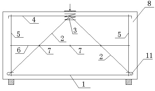
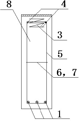
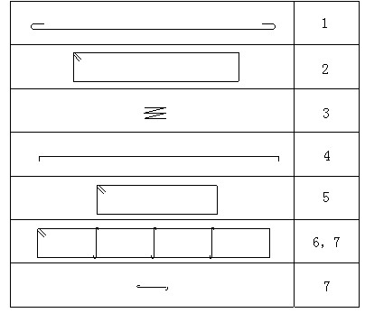
[0029] Such as figure 1 , figure 2 , image 3 , Figure 4 As shown, a reinforcement method for reinforced concrete deep beams comprises the following steps:

[0030] The first step: horizontally arrange the longitudinal tension reinforcement 1 at the bottom of the deep beam; the ends of the longitudinal tension reinforcement 1 are respectively provided with hooks 11

[0031] Step 2: One end of the two groups of obliquely compressed steel bars 2 is respectively fixed in the hooks at both ends of the obliquely compressed steel bar 1 on the same side, and the other end is overlapped with each other at the top of the deep beam. The tension bars 1 form a triangular arrangement, and the top is covered by the spiral bars 3 at the overlapping position;

[0032] Step 3: After passing through the spiral bar 3, the top distribution reinforcement 4 is lap...


PUM

PropertyMeasurementUnit
thicknessaaaaaaaaaa

Abstract

The invention discloses a steel bar arrangement method and a steel bar arrangement device for a reinforced concrete deep beam, relates to the technical field of civil engineering, in particular to the technical field of the steel bar arrangement method for the reinforced concrete deep beam by using compression steel bars. The method comprises the following steps of: arranging a filling block on the part where the reinforced concrete deep beam bears concentrated force; arranging longitudinal tensile steel bars, oblique compression steel bars and other steel bars in the reinforced concrete deep beam, wherein the longitudinal tensile steel bars are arranged along the length direction of two supports and the ends of the longitudinal tensile steel bars correspond to the supports respectively; and one end of each of two groups of oblique compression steel bars is respectively connected with the two ends of each longitudinal tensile steel bar, while the other end is intersected with a position corresponding to the filling block; after all steel bar cages are bound, pouring concrete to make the longitudinal tensile steel bars and the oblique compression steel bars form three-pin rigid frames borne by the supports so as to bear top concentrated load on the filling block. The method and the device realize a clearer stress path and more regular stress distribution in the deep beam; and compared with the conventional steel bar arrangement method, the method can still fulfill the aim of achieving the same bearing capacity under the condition of greatly reducing the number of used steel bars.

Description

[0001] technical field [0002] The invention relates to the technical field of civil engineering, in particular to the technical field of a tension-oblique compression reinforcement device utilizing reinforced concrete deep beams. [0003] Background technique [0004] "Code for Design of Concrete Structures" (GB50010-2002) stipulates that simply supported beams with a ratio of span to height l / h≤2 and continuous beams with l / h≤2.5 are deep beams. Due to the large size of the deep beam structure and the complex force of the internal system, there are many types of failure of the deep beam. There are three main failure forms of deep beams: one is bending failure; the other is shear failure; the third is local compression or anchorage failure. In order to resist various damages, the reinforcement of deep beams is more complicated. The current code suggests adopting the cross-section internal force method for design, and configuring structural reinforcement for deep bea...

Claims


Application Information

Patent Timeline
Patent Type & Authority Applications(China)
IPC IPC(8): E04G21/12E04C3/20
Inventor 杨文军洪宝宁
Owner HOHAI UNIV
Learn More