Floating type wind energy receiving device

A receiving device and floating technology, applied in the field of floating wind energy receiving device, can solve the problems of heavy weight, low wind energy density, increase investment in power transmission and transformation system, etc., and achieve the effect of small investment and small unit investment

Inactive Publication Date: 2011-01-26
CHINA NAT COAL GROUP CORP
View PDF0 Cites 12 Cited by
  • Summary
  • Abstract
  • Description
  • Claims
  • Application Information

AI Technical Summary

Problems solved by technology

[0006] 1. A complex steering control system is required, the bearing is subjected to huge shear stress, the friction consumption is also large, and there is a dead point
[0007] 2. As the kite is retracted and released, pulsating shocks appear continuously, resulting in pulsating electricity, which increases the investment in the power transmission system and the complexity of the working process
[0008] 3. The energy density of wind power is already very low, and power is consumed to fly the kite, which further reduces the utilization rate of wind energy
[0009] 4. This technology requires a high degree of automatic computer control, and there must be accurate wind measuring devices around it. Since the work is constantly changing, there is no stable state (not only can it not work in a stable state, but the kite will fall), it is more flying than airplanes and missiles. The process (except for take-off or hitting the target, all work in an approximate steady state) is complicated
Therefore, the stability of the technology is poor
[0010] 5. The part of the kite or paraglider needs to increase the rope mechanism, which increases the weight of the lifting mechanism, making it more difficult to fly the kite into the sky
[0011] 6. Poor aerodynamics, almost entirely drag type, low efficiency
[0012] 7. The operation is complicated and the practicability is poor: how to fly a kite the size of a football field with a rope thousands of meters long is a problem
These power generating devices also have some common shortcomings: 1, because the wind energy receiving device and the generating mechanism are all floating in the air, the structure of the wind power generating device is complicated and the weight is heavy, which restricts the further improvement of its power; 2, the volume 1. The power generation devices with relatively large weight are all set in the air. Once they crash, they will pose a threat to the safety of the ground, and the safety is poor; The wind energy received by the wind in some directions is low, and the variability of high-air flow restricts its effective use of wind energy. 4. It is necessary to install additional floating devices in order to lift the power generation device into the sky, which increases the manufacturing cost.

Method used


Image

  • Floating type wind energy receiving device
  • Floating type wind energy receiving device
  • Floating type wind energy receiving device

Examples


Embodiment Construction

[0055] The present invention will be described in detail below in conjunction with the accompanying drawings. The description in this part is only exemplary and explanatory, and should not have any limiting effect on the protection scope of the present invention.

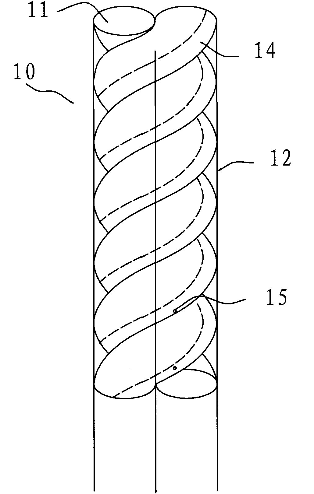
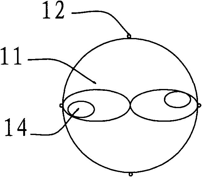
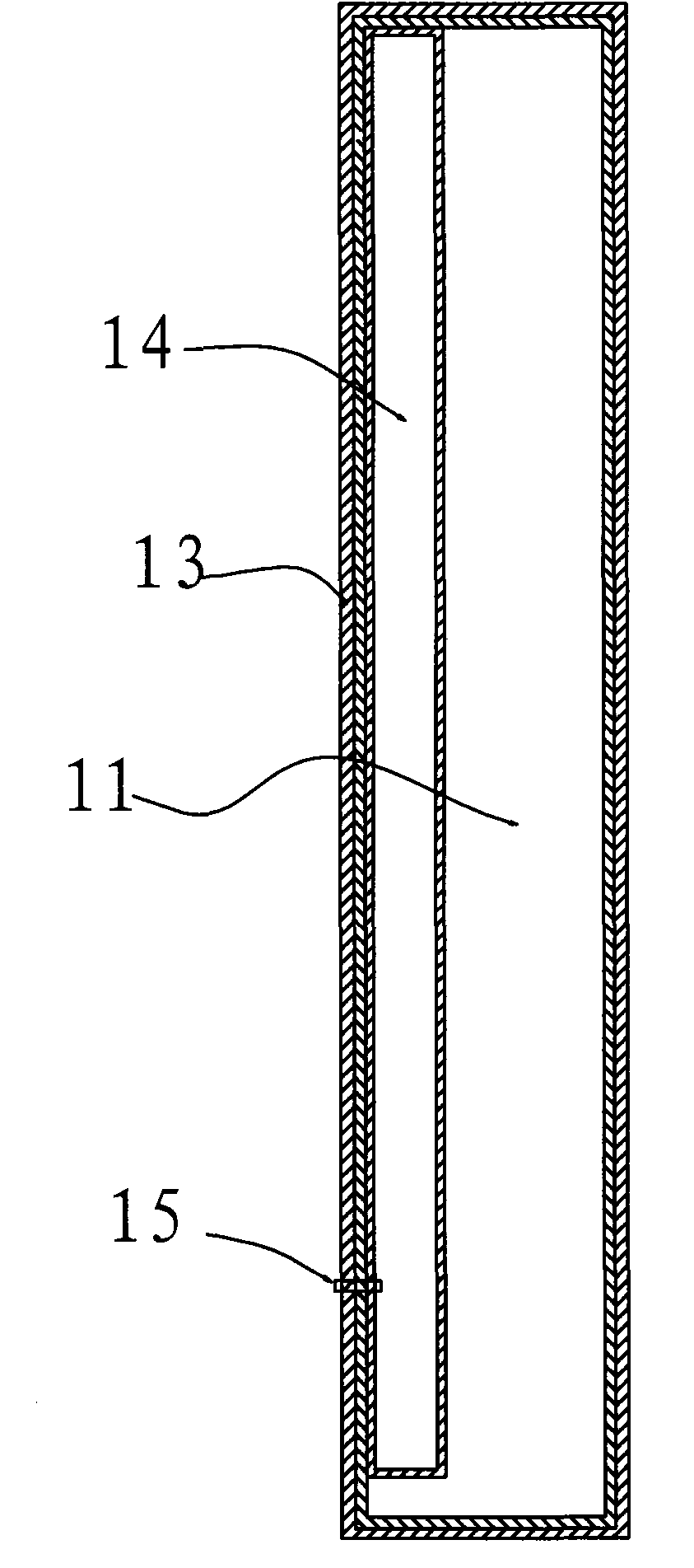
[0056] figure 1 Shown is a schematic view of the side structure of the first embodiment of the present invention, figure 2 Yes figure 1 top view. like figure 1 , figure 2 Shown, the floating type wind energy receiving device of the present invention, it comprises:

[0057] A spiral airbag 10 is formed by two columnar airbags 11 intertwined with each other to form a double helical surface, and the joints of the two columnar airbags 11 are connected to each other, and light gases such as hydrogen or helium are installed inside; the connection between the two columnar airbags 11 can use Internal drawcord or direct bonding.

[0058] Four traction ropes 12 are arranged longitudinally along the spiral airbag 10 re...


PUM


Abstract

The invention discloses a floating type wind energy receiving device, which comprises a helical air sac and a plurality of pulling ropes, wherein the helical air sac is provided with a double helix surface and contains light gas; the pulling ropes are respectively and vertically distributed along the helical air sac, and are connected to each convex outer surface of the air sac in sequence; the lower end of each pulling end is connected with a driving device used for driving a generator; the double helix surface of the helical air sac can be formed by winding two columnar air sacs which are connected with each other; the double helix surface of the helical air sac also can be formed by orderly pulling the pulling ropes arranged in a cylindrical air sac and relative to the surface; each two pulling ropes are orderly staggered into an included angle to form helical distribution. The floating type wind energy receiving device has the advantages of simple structure, convenient operation and control, lower cost, light weight and high use safety, and can effectively utilize high altitude wind energy.

Description

technical field [0001] The present invention relates to a wind energy generating equipment, in particular to a floating wind energy receiving device which utilizes high air flow to generate power. Background technique [0002] The wind energy receiving device is a device that converts wind energy into rotational mechanical energy. At present, the commonly used wind energy receiving device is the wind blade, which is installed on the top of the wind tower to drive the generator to generate electricity. Limited by the height of the wind tower, this kind of wind energy receiving device can only receive and utilize wind energy near the ground, and because the wind speed on the ground is low and the energy is small, if you want to increase the power of wind power generation, you can only use large-sized wind power as much as possible. The blades increase the wind-receiving area, which also brings about a sharp increase in cost, and the size of the wind blades cannot be increased...

Claims


Application Information

Patent Timeline
Patent Type & Authority Applications(China)
IPC IPC(8): F03D9/00F03D5/06F03D11/00
CPCY02E10/722Y02E10/70Y02E10/72
Inventor 张阳
Owner CHINA NAT COAL GROUP CORP
Why Eureka
Try Eureka