Photo-epilation device

一种设备、控制设备的技术,应用在光脱毛领域,能够解决永久性怀疑等问题,达到小尺寸的效果

Active Publication Date: 2011-01-26
KONINK PHILIPS ELECTRONICS NV
View PDF2 Cites 19 Cited by
  • Summary
  • Abstract
  • Description
  • Claims
  • Application Information

AI Technical Summary

Problems solved by technology

Authors observe long-term hair removal, but they cast doubt on the permanence of their method

Method used


Image

  • Photo-epilation device
  • Photo-epilation device

Examples


Embodiment Construction

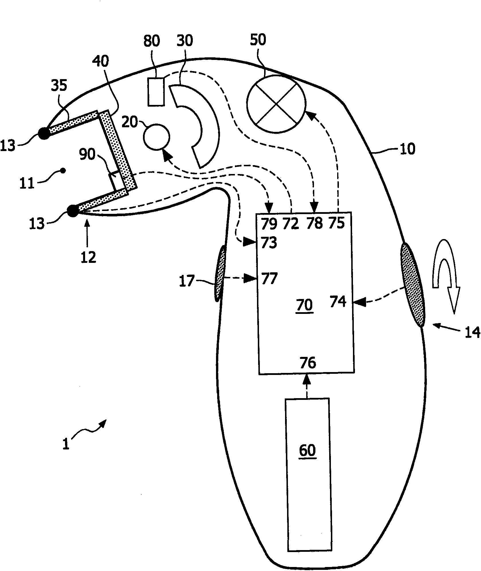
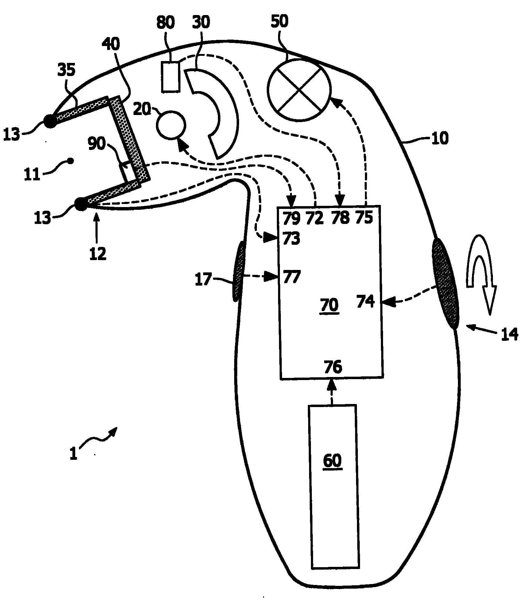
[0014] figure 1 A hand-held photoepilation device 1 according to the invention is schematically illustrated. The device comprises a housing 10 which has dimensions similar to those of a shaving device. The housing 10 houses at least one broadband intense light source 20 . The light source 20, hereinafter also referred to as "lamp", is suitably implemented as a xenon flash lamp, but other types of lamps can also be used, as long as they produce a spectrum suitable for achieving photoepilation. Since xenon flash lamps are known per se, no further explanation is necessary.

[0015] The housing 10 is substantially closed, but has a window 11 (although the housing may have multiple windows) for enabling the light generated by the lamp 20 to exit the housing. The edge of the window 11 will be called the mouth 12 of the device 1 . The preferred shape of the window is substantially rectangular, and the preferred dimensions are about 30mm by about 10mm. However, in order to treat ...


PUM


Abstract

A photo-epilation device (1) comprises: a hand-held housing (10) with at least one window opening (11); a lamp (20) accommodatedin the housing for generating light having a spectralrange from approximately 575nm to approximately 1700nm;and a control device (70) for driving the lamp (20). The lamp is switched on in brief pulses having a pulse duration in the range from l.1ms to 1.9ms, preferably about 1.8ms, and a pulse repetition frequency in the range from 0.1Hz to 0.5Hz. The fluence on skin level is in the range from 2 to 7J / cm2, dependenton the skin type, particularlyfrom: 5 to 7J / cm2 for skin types I, II, III; 4 to 6J / cm2 for skin type IV; 3 to 5J / cm2 for skin type V;and 2 to 3J / cm2 for skin type VI.

Description

technical field [0001] The present invention generally relates to photoepilation, ie the (temporary or permanent) removal of hair by light. Background technique [0002] Photoepilation is known per se; by way of example, reference is made to US-5,735,844. Light from a suitable light source (laser; flashlight) is absorbed by the melanin in the hair and / or follicles. The absorbed light is converted into heat. This heat damages and even destroys the hair follicle. Hair falls out and new growth is delayed or even prevented altogether. [0003] Light is usually applied in pulses. Several parameters play a role in hair removal efficiency: pulse duration, pulse repetition frequency, wavelength or spectral range of light, and fluence (or energy density, expressed in J / cm 2 express). In attempting permanent hair removal and thus destruction of the hair follicle, the literature reports applications of up to 60 J / cm in pulses ranging from a few ms to hundreds of ms 2 integral fl...

Claims


Application Information

Patent Timeline
Patent Type & Authority Applications(China)
IPC IPC(8): A61B18/20A61B17/00A61B18/18A61B19/00A61N5/06
CPCA61B2018/202A61B2018/00476A61B18/203A61B2017/00154A61B2018/1807A61N2005/0644A61N2005/0654A61B2017/00181A61B2019/465A61N5/0617A61B2018/00452A61B2090/065A45D26/00A61B17/00A61N5/06
Inventor A·M·纽杰斯L·J·T·埃弗斯-德克斯
Owner KONINK PHILIPS ELECTRONICS NV
Why Eureka
Try Eureka