
A shoe mold

A technology for making shoe molds and mold cores, which is applied to household appliances, other household appliances, and household components, etc., and can solve problems such as low guiding accuracy, easy damage, and high defective rate

Active Publication Date: 2016-01-13
东莞久仁模具设计有限公司
View PDF2 Cites 0 Cited by
  • Summary
  • Abstract
  • Description
  • Claims
  • Application Information

AI Technical Summary

Problems solved by technology

[0002] In the existing shoe-making mould, after injection molding of the shoe material mold, the injection port must be blocked. The existing blocking device is composed of a sealing rod. The socket is an interference fit, the sealing rod is not a standard fit, the sealing rod is easy to separate from the mold, and is easy to wear, resulting in material running, leakage, high defective rate, and backflow. At the same time, its positioning device consists of a positioning column and a positioning The hole structure, the positioning post is inserted in the fixing hole, which is an interference fit at room temperature, but in the heated state, due to the different materials of the mold and the positioning post device, different expansion occurs, and the positioning post device is easy to loose. There are also guide columns used, which are composed of cylinders. The cylinders pass through the upper mold, the lower mold, and the mold core to play the role of guiding sliding and positioning. Guidance accuracy is not high

Method used


Image

  • A shoe mold
  • A shoe mold
  • A shoe mold

Examples


Embodiment 1

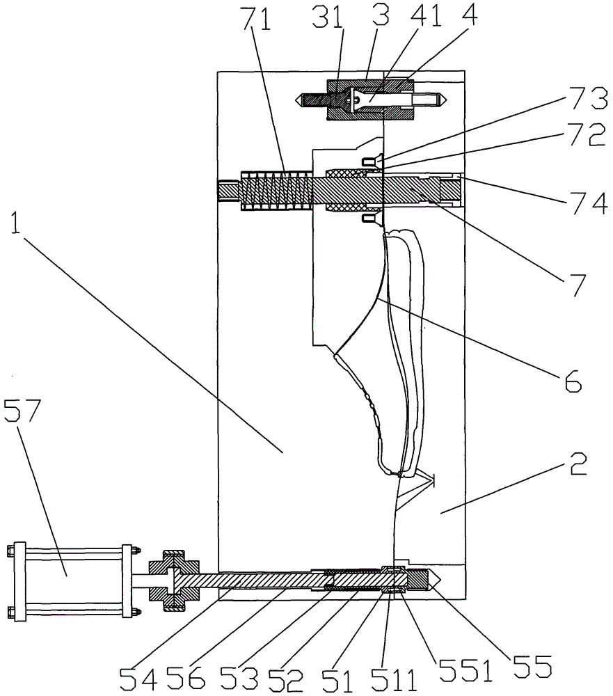
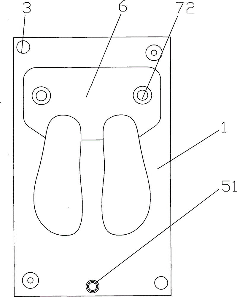
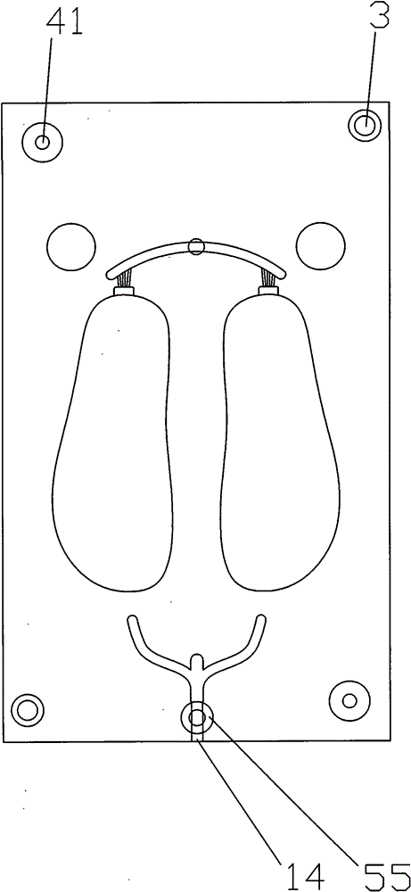
[0017] Such as figure 1 , figure 2 , image 3 , Figure 4 Shown, a kind of shoemaking mould, by upper mold 1, lower mold 2 and mold core 6 between upper mold 1 and lower mold 2, the injection molding mouth 14 place between described upper mold 1 and lower mold 2 is provided with Blocking device 5, each of the four corners of the upper mold 1 and the lower mold 2 is provided with a positioning column device, and the upper mold 1, the lower mold 2, and the core 6 are pierced with an SPR guide column device. Such as Figure 4 As shown, the blocking device consists of a guide sleeve 51, a sealing rod 52 arranged in the guide sleeve 51, a fixed sleeve 53 sleeved on the top of the sealing rod 52, and an adjustment rod 54 whose lower end is threadedly connected to the upper end of the sealing rod 52. 1. An inserting sleeve 55 arranged below the guide sleeve 51 is formed. The guide sleeve 51 is arranged in the installation hole of the upper mold 1. A guide hole 56 is provided abo...

Embodiment 2

[0019] Such as figure 1 , figure 2 , image 3 , Figure 5 As shown, the positioning column device includes a positioning sleeve device installed on the upper mold 1, a positioning column device installed on the lower mold 2 and matched with the positioning sleeve device, and the positioning sleeve device is composed of a barrel-shaped positioning sleeve 3, a set Composed of locking screws 31 inside the barrel-shaped positioning sleeve 3, the locking screw 31 fixes the barrel-shaped positioning sleeve 3 to the upper mold 1, the positioning sleeve device is arranged in the concave hole of the upper mold 1, and the positioning column device It consists of a hollow positioning column 4 and a locking screw 41 arranged in the hollow positioning column 4 , the locking screw 41 fixes the hollow positioning column to the lower mold 2 , and the positioning column device is arranged in the concave hole of the lower mold 2 . The locking screws 31, 41 are hexagon socket screws, the pos...

Embodiment 3

[0021] Such as figure 1 , figure 2 , image 3 , Figure 6 As shown, the SPR guide column device is composed of a cylinder 7 pierced through the upper mold 1, the mold core 6, and the lower mold 2. The upper end of the cylinder 7 is provided with threads, and the upper mold 1 is provided with a sinker. hole, the bottom of the counterbore is provided with a threaded hole, and the threaded hole is threadedly matched with the upper end of the cylinder 7, and the upper part of the cylinder 7 is provided with a compression spring 71, and one end of the compression spring 71 acts on the mold core 6, The other end acts on the bottom of the counterbore, and the mold core 6 can be ejected. The middle part of the cylinder 7 is covered with a guide sleeve 72, and the guide sleeve 72 is fixed in the through hole of the mold core 6. The through hole on the lower side of the mold core 6 A locking screw 73 is installed at the position, and the locking screw 73 presses the guide sleeve 72 ...


PUM


Abstract

The invention relates to the field of molds, in particular to a novel shoe making mold, which consists of an upper mold, a lower mold and a mold core between the upper mold and the lower mold, wherein a blocking device is arranged at the injection opening between the upper mold and the lower mold; each of the four corners of each of the upper and lower molds has a positioning post device; and an SPR guide post device is inserted into the upper mold, the lower mold and the mold core. With the structure, the mold has the advantages that: the precision of the blocking device is high; the mold is a combined part; the rate of finished products is high; the maintenance and detachment are convenient; looseness is prevented; the guide sliding of the core mold is smooth and precise; damage is prevented; and products can be processed automatically.

Description

technical field [0001] The invention relates to the field of molds, in particular to a shoemaking mold. Background technique [0002] In the existing shoe-making mould, after injection molding of the shoe material mold, the injection port must be blocked. The existing blocking device is composed of a sealing rod. The socket is an interference fit, the sealing rod is not a standard fit, the sealing rod is easy to separate from the mold, and is easy to wear, resulting in material running, leakage, high defective rate, and backflow. At the same time, its positioning device consists of a positioning column and a positioning The hole structure, the positioning post is inserted in the fixing hole, which is an interference fit at room temperature, but in the heated state, due to the different materials of the mold and the positioning post device, different expansion occurs, and the positioning post device is easy to loose. There are also guide columns used, which are composed of c...

Claims


Application Information

Patent Timeline
Patent Type & Authority Patents(China)
IPC IPC(8): B29C45/26B29C45/28B29L31/50
Inventor 谢抗承
Owner 东莞久仁模具设计有限公司
Learn More