
Backlight device of display

A backlight device and display technology, applied in the direction of lighting devices, fixed lighting devices, light guides of lighting systems, etc., can solve the problems of reducing the optical taste of the visible area of ​​the display quality, reducing the display quality of the display, and uneven brightness of the display screen

Inactive Publication Date: 2011-02-02
CHI LIN TECH CO LTD
View PDF4 Cites 5 Cited by
  • Summary
  • Abstract
  • Description
  • Claims
  • Application Information

AI Technical Summary

Problems solved by technology

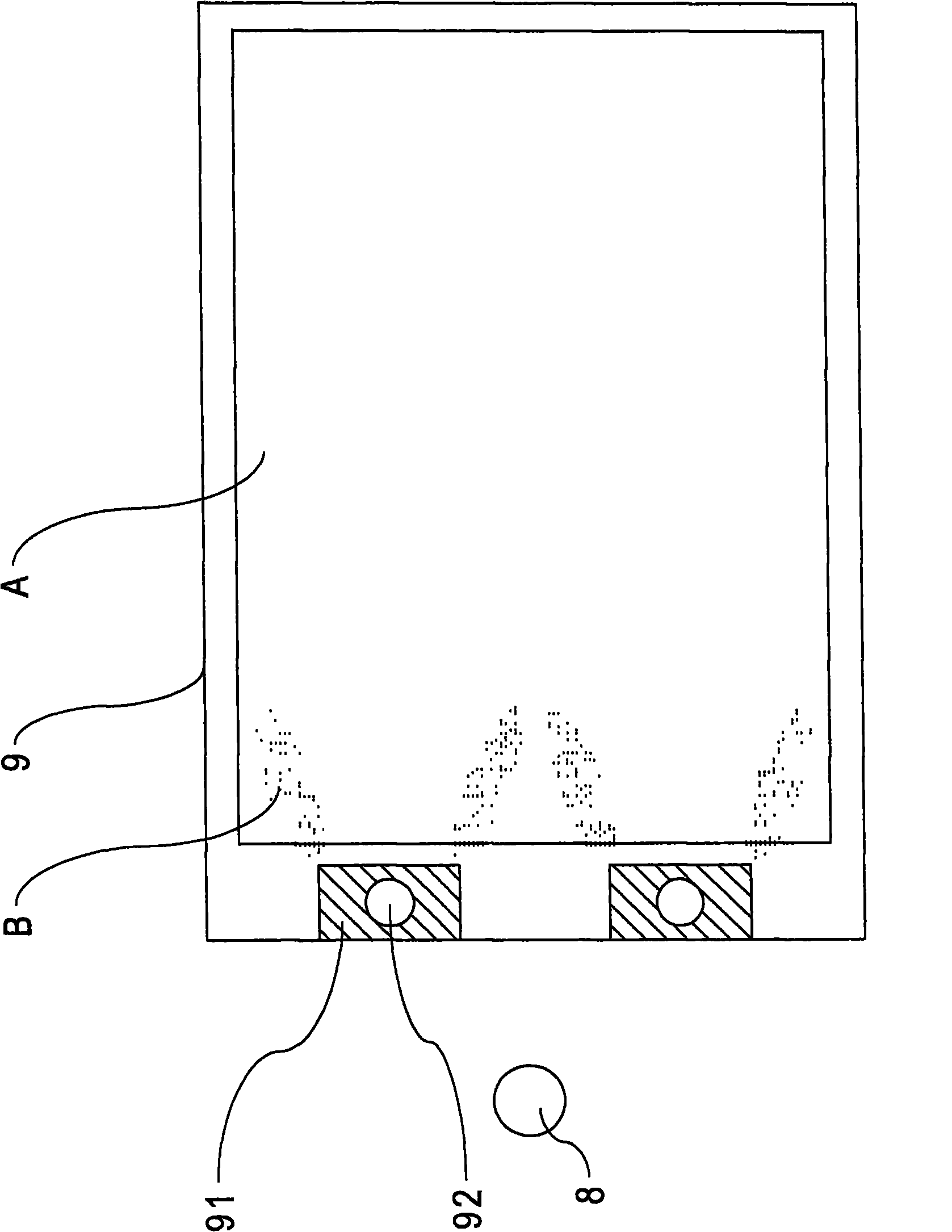
The light emitted by the light source 8 will enter the light guide plate 9, and the area of ​​part A is the visible area A of the display quality, but because the light emitted by the light source 8 into the light guide plate 9 will leak from the concave position 91 partially unevenly, a phenomenon occurs. Light leakage (light leakage), such as figure 1 As shown in B in the backlight device, the phenomenon of uneven brightness of the display screen (Mura) will occur in this backlight device, which will further reduce the optical taste of the visible area of ​​its display quality
[0004] Therefore, it is necessary to provide a backlight device that can provide uniform brightness to solve the above-mentioned related problems, and can prevent partial light from leaking into the visible area and reduce the display quality of the display.

Method used


Image

  • Backlight device of display
  • Backlight device of display
  • Backlight device of display

Examples


Embodiment Construction

[0034] Since the present invention discloses a backlight device of a display, the optical principle and basic structure used therein are already understood by those with ordinary knowledge in the relevant technical field, so the following description will not be described completely. At the same time, the drawings referred to in the following text express structural schematic diagrams related to the characteristics of the present invention, and are not and need not be drawn completely according to the actual size, as described earlier.

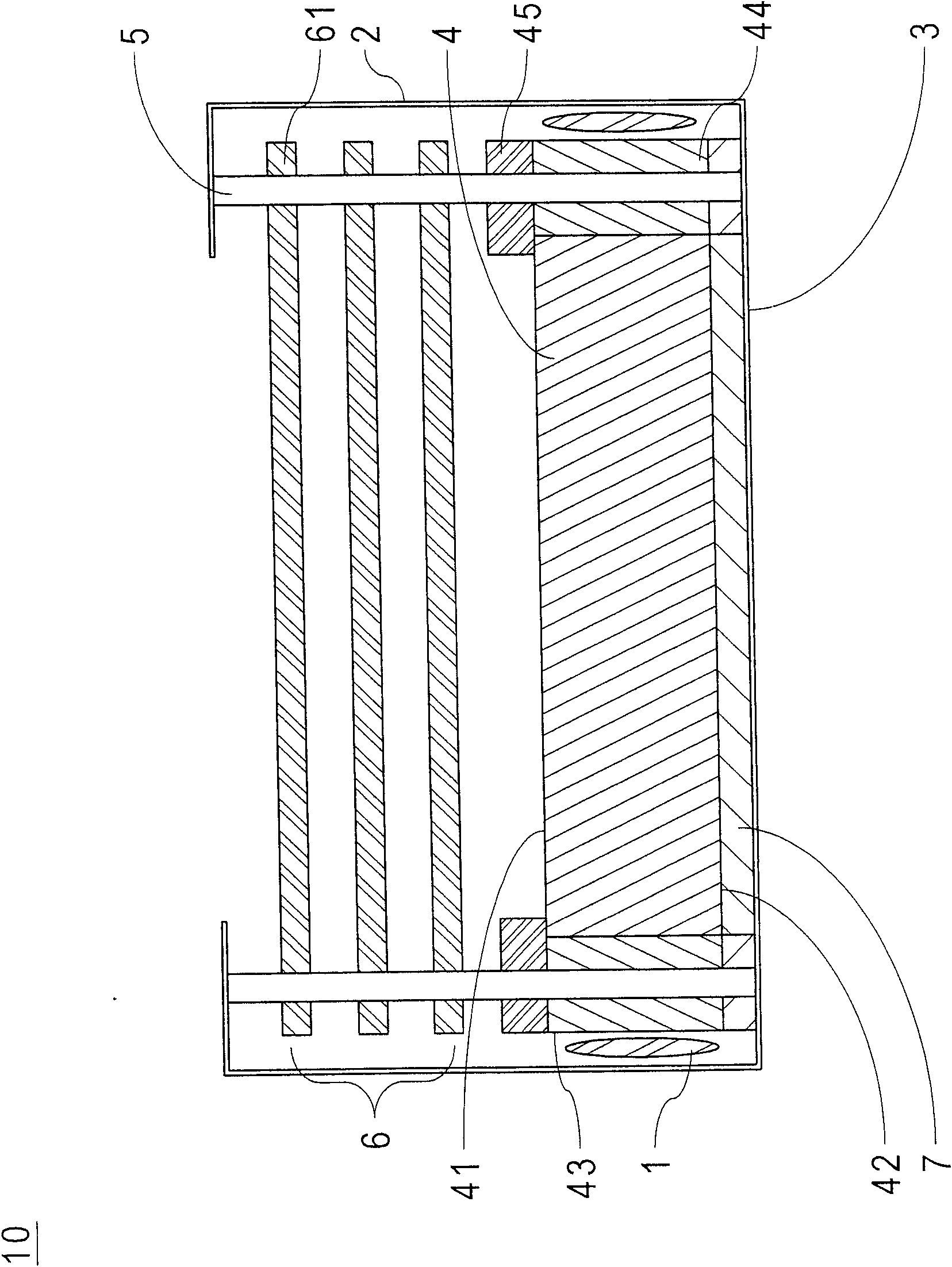
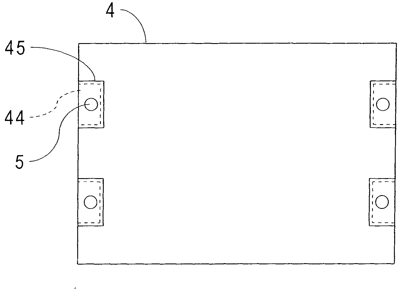
[0035] Please refer first figure 2 , Which is the first preferred embodiment of the present invention, is a display backlight device 10, which mainly includes at least one light source device 1, a housing 2, a light guide plate 4, a plurality of fixing structures 5 and a plurality of shading elements 45 . The housing 2 includes a bottom plate 3. The light guide plate 4 has an upper surface 41, a lower surface 42 and a side surface 43, please re...


PUM


Abstract

The invention provides a backlight device of a display, wherein the backlight device mainly comprises at least one light source device, a casing, a light guide plate, a plurality of fixed structures and a plurality of light shielding elements. The casing comprises a bottom plate. The light guide plate is provided with an upper surface, a lower surface and a side surface, the edge of the light guide plate is provided with a plurality of openings and the lower surface thereof faces the casing and is arranged on the casing. The fixed structures are arranged on the bottom plate in a convex manner, corresponding to the openings of the light guide plate, and penetrate the openings of the light guide plate. The light shielding elements have a light penetration rate less than 50% and are arranged at the openings of the light guide plate.

Description

Technical field [0001] The present invention relates to a backlight device, in particular to a backlight device applied to a liquid crystal display in a flat panel display. Background technique [0002] In recent years, with the maturity of optoelectronic technology and semiconductor manufacturing technology, flat panel displays (Flat Panel Display) have flourished. Among them, liquid crystal displays (Liquid Crystal Display / LCD) are based on their low-voltage operation, no radiation scattering, light weight, and small size. Advantages, it has gradually replaced traditional cathode ray tube displays and has become the mainstream of display products in recent years. The liquid crystal display mainly includes a liquid crystal display panel (Liquid Crystal Display Panel) and a backlight device (backlight module), wherein the backlight device is used to provide the surface light source required by the liquid crystal display panel, and the light guide plate (Light Guide Plate) is used...

Claims


Application Information

Patent Timeline
IPC IPC(8): F21V11/00G02F1/13357F21S8/00G02F1/1333F21V13/00F21V8/00
Inventor 王子昌林东邦
Owner CHI LIN TECH CO LTD
Learn More