
Method for controlling a lighting device

A technology for lighting devices and controllers, which is applied to lighting devices, output power conversion devices, and lamp circuit layout, etc., which can solve problems such as high installation costs and unreliable radio interference spectrum, and achieve the effect of low installation costs

Inactive Publication Date: 2014-10-22
ABB (SCHWEIZ) AG
View PDF4 Cites 0 Cited by
  • Summary
  • Abstract
  • Description
  • Claims
  • Application Information

AI Technical Summary

Problems solved by technology

In the case of separation of the operating part from the luminaire, multiple (at least four) wiring lines are required, which results in relatively high installation expenditures
Furthermore, the pulse width modulation (Pulweitenmodulation, PWM) usually used in LED brightness control produces an unreliable radio interference spectrum when wiring lines of several meters are used

Method used


Image

  • Method for controlling a lighting device
  • Method for controlling a lighting device
  • Method for controlling a lighting device

Examples


Embodiment Construction

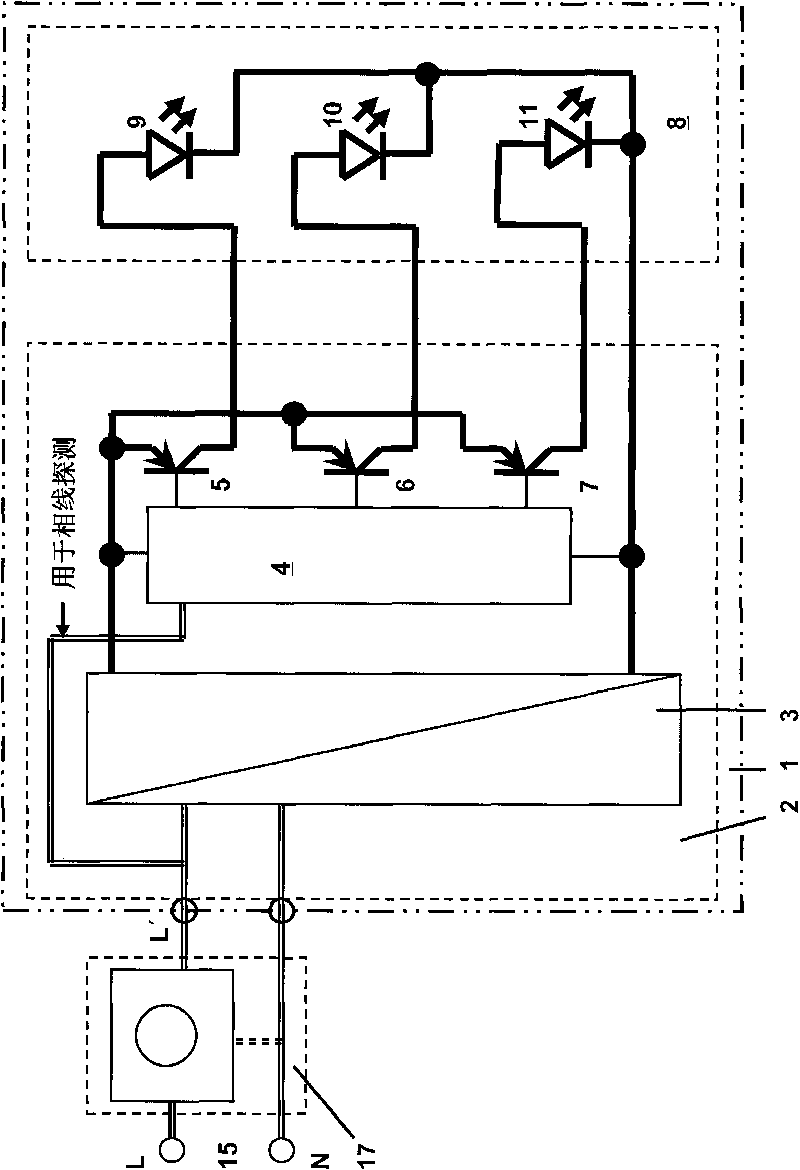
[0072] figure 1 A circuit diagram of a lighting device is shown, the lighting device is preferably connected to the controller through at least one wiring line, and the lighting device is provided with a plurality of lamps (preferably LEDs) of different colors. The input end of the controller 17 (manipulator, operating element) is connected to the phase line L and the neutral line N of the AC power supply 15 (230V AC voltage). The output voltage obtained at the output of the controller 17 is denoted below as rectified phase L′ and corresponds to the input voltage of the lighting device 1 . Furthermore, the lighting device 1 is also connected to the neutral line N. As shown in FIG.

[0073] A lighting device 1 consisting of an RGB-LED lighting device (R=red / G=green / B=blue) comprises two main components or functional units assembled together, namely a built-in part 2 and a plurality of lamps, preferably LED ) 9, 10, 11, wherein the two main components are detachably connected ...


PUM


Abstract

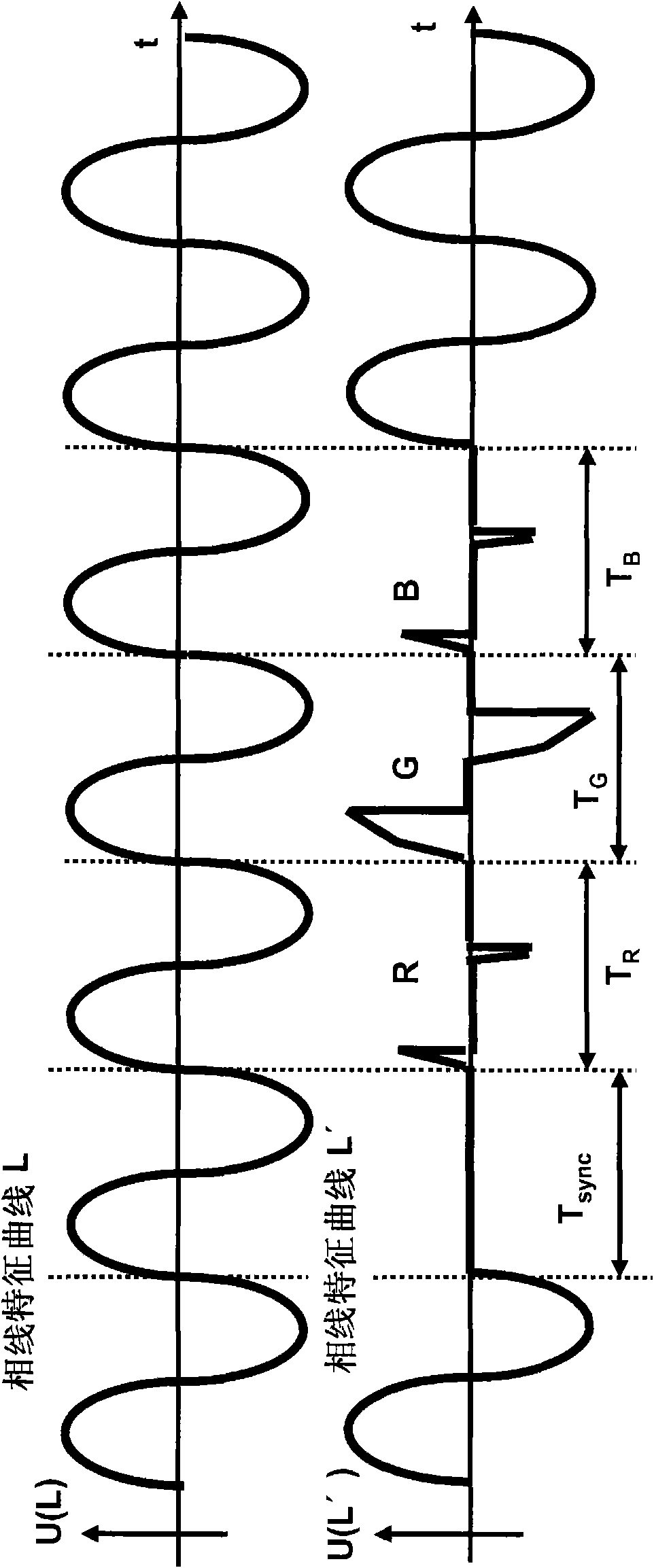
The method involves starting an evaluation routine by a control module (4) of an associated light i.e. RGB-LED light (1), after reception of a synchronization signal in order to remove an information network wave of a phase of a transferred desired intensity information signal. The intensity information signal is stored and is used for controlling a light unit e.g. red LED (9), green LED (10) and blue LED (11) and white LED, up to occurrence of the synchronization signal. A power module is controlled by the control module based on the stored intensity information signal.

Description

technical field [0001] The present invention relates to a method for controlling a lighting device, and the present invention can especially be used for RGB-LEDs (R=red LED / G=green LED / B=blue LED) to realize controlling RGB-LED lighting devices, however that It can also be used with white LEDs to realize the control of white LED lighting devices. Background technique [0002] Document EP 1575341 B1 discloses a dimmer with operating parts, which controls at least one power module, so as to adjust the desired brightness of a luminaire, wherein [0003] - a control lever is provided as the operating element, which can be swiveled and / or rotated and / or pushed into different positions, thereby actuating the switching connection of the switching device, which controls a A controller whereby, by means of a power module that separates each color channel, in addition to adjusting the required brightness of the luminaire, additionally adjusts the desired light color of the luminaire;...

Claims


Application Information

Patent Timeline
Patent Type & Authority Patents(China)
IPC IPC(8): H05B37/02H02M1/08H05B44/00
CPCH05B37/0263H05B33/086H05B45/20H05B47/185
Inventor 沃尔夫冈·沙伦贝格斯塔凡·维斯科罗伯特·察普
Owner ABB (SCHWEIZ) AG
Learn More