Blow shoe mould

A shoe mold and mold cavity technology, which is applied in the field of blown shoe molds, can solve the problems of insufficient foaming, waste of materials, poor flexibility of foamed products, etc., and achieve the effect of sufficient foaming, reduced force, and less material consumption

Active Publication Date: 2011-02-09
JINJIANG ZHONGTIAN MOLD
View PDF7 Cites 4 Cited by
  • Summary
  • Abstract
  • Description
  • Claims
  • Application Information

AI Technical Summary

Problems solved by technology

[0004] The invention provides an air blowing shoe mold, the main purpose of which is to overcome the shortcomings of insufficient foaming, waste of materials and poor flexibility of foamed products in the existing air blowing shoe mold

Method used


Image

  • Blow shoe mould
  • Blow shoe mould
  • Blow shoe mould

Examples


Embodiment Construction

[0015] Specific embodiments of the present invention will be described below with reference to the accompanying drawings.

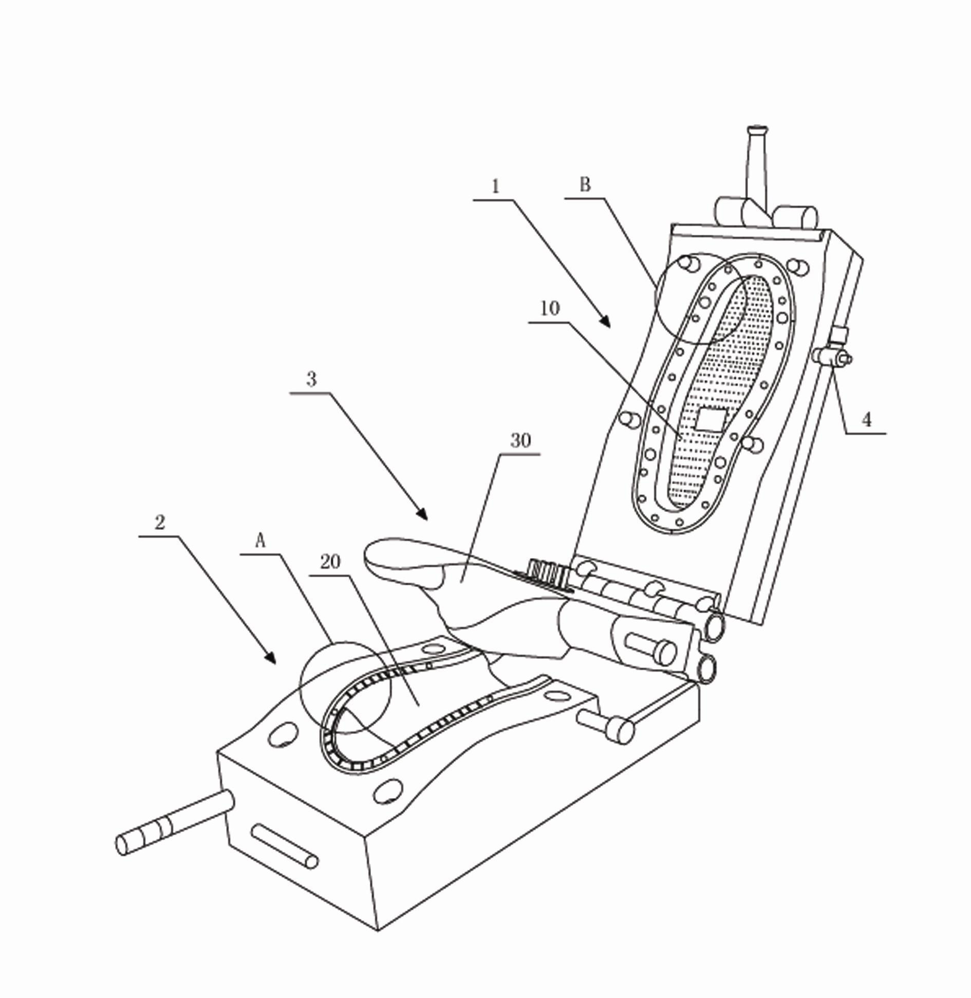
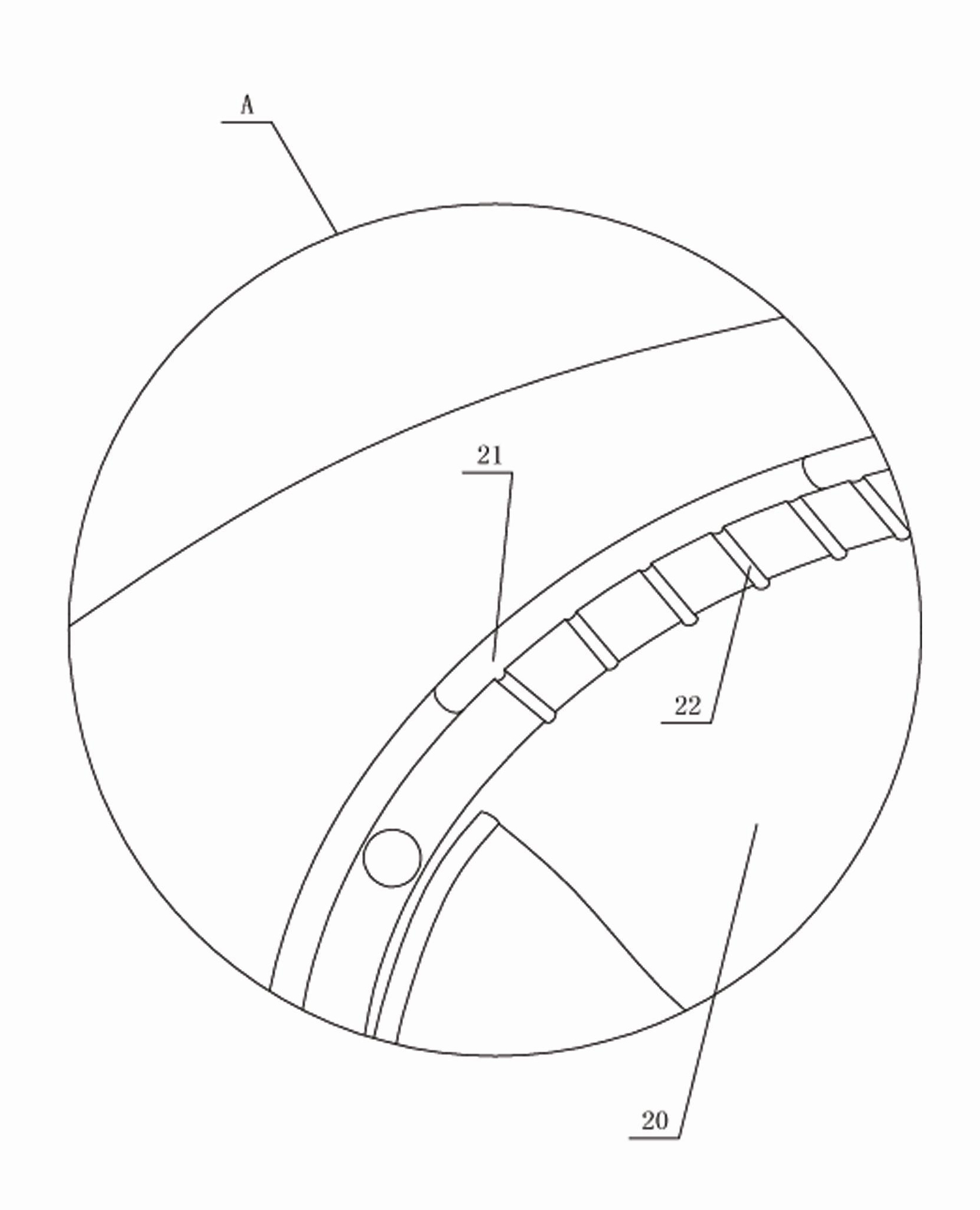
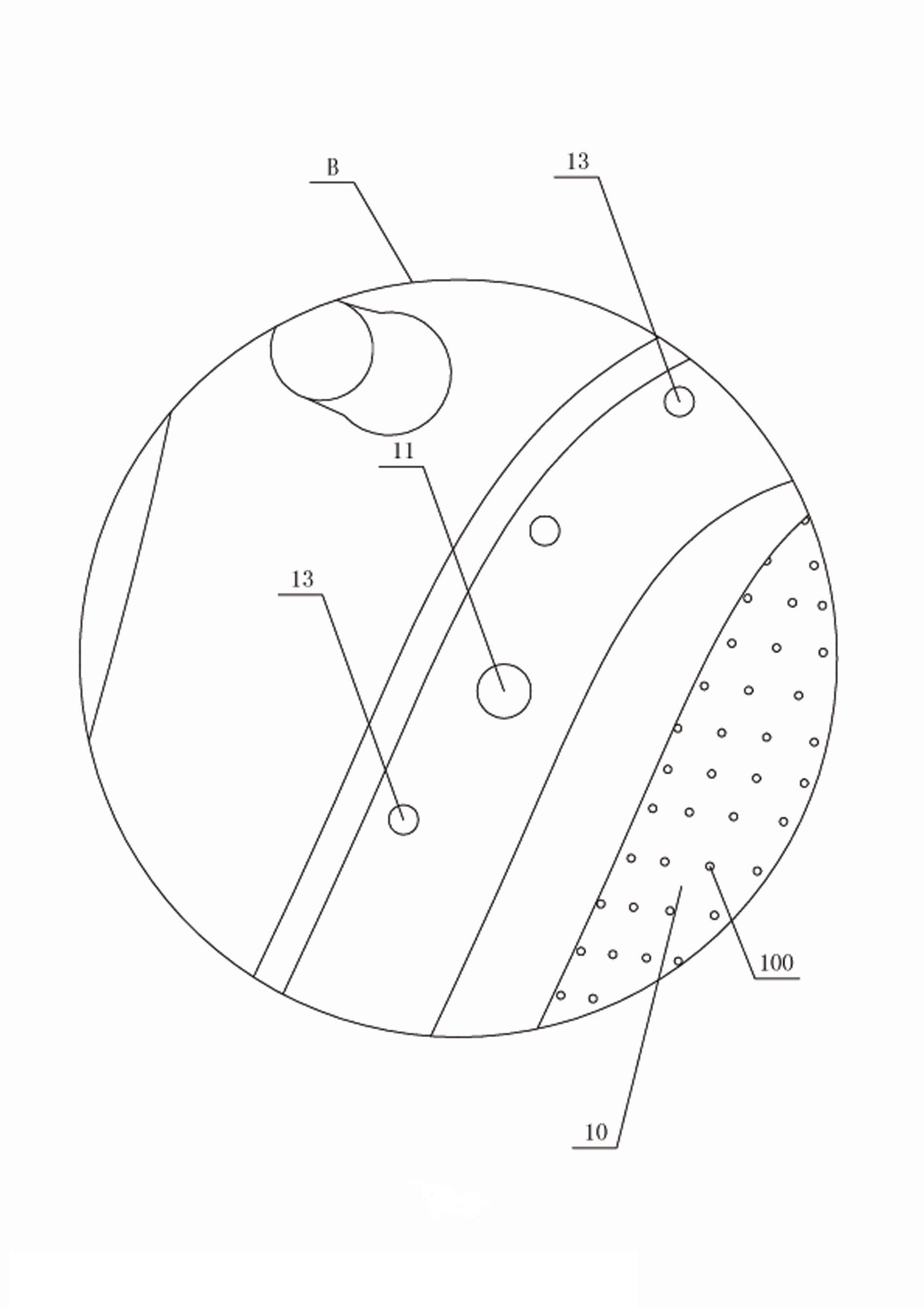
[0016] refer to figure 1 , figure 2 , image 3 , Figure 4 , a kind of blowing shoe mold, comprises the upper die 1 that has upper mold cavity 10, has the lower mold 2 of lower mold cavity 20, is located at the mold core 3 between upper mold 1 and lower mold 2 and is used for upper mold The exhaust port 4 through which the gas in the mold cavity 10 and the lower mold cavity 20 is discharged, the rear edge of the mold core 3 is hinged with the lower mold 2, the rear edge of the upper mold 1 is hinged with the rear edge of the mold core 3, The upper mold 1 is provided with a shot channel 11 and an air intake channel, and the air intake channel includes an air inlet 120 arranged at the top 12 of the upper mold, and a plurality of holes connected with the air inlet 120 and densely distributed on the top of the upper mold cavity 10 . A small hole 100 and ...


PUM


Abstract

A blow shoe mould comprises an upper mould with an upper mould cavity, a lower mould with a lower mould cavity, and a mould core installed between the upper and lower moulds; the blow shoe mould further comprises an air discharging outlet installed on the upper mould for discharging air in the upper and lower mould cavity; the rear side of the mould core is hinged with the lower mould; the rear side of the upper mould is hinged with the rear side of the mould core; the upper mould is provided with a material injection passage and an air inlet passage; the air inlet passage comprises an air inlet installed on the top of the upper mould and a plurality of small holes communicated with the air inlet and densely distributed on the top of the upper mould cavity; the air discharging outlet is installed on the upper mould; the air inlet passage further comprises an edge passage formed by butting the upper and the lower passages; the upper passage is installed on the periphery of the upper mould cavity and communicated with the air inlet; and the lower passage is installed on the periphery of the lower mould cavity and communicated with the lower mould cavity. The shoe mould uses a plurality of small holes to blow with the lower passage in different directions; the air discharging outlet is installed on the upper mould; thus, the gas can be sealed in the mould cavity so that foam materials such as PVC can be fully foamed.

Description

technical field [0001] The invention relates to a shoemaking mold, in particular to an air blowing shoe mold. Background technique [0002] Existing air-blowing shoe molds generally include an upper mold, a lower mold and a mold core located between the upper mold and the lower mold. One side edge of the mold core is hinged with the lower mold. The side edge is hinged, and the upper mold is provided with an injection channel and an air intake channel. The lower mold is composed of holes, and the lower mold is provided with an air outlet channel. [0003] The blowing injection molding process is that foam materials such as PVC enter the mold cavity formed between the upper mold and the lower mold through the injection channel of the upper mold, and the high-pressure gas enters through the air inlet, and then blows out through multiple small holes. The gas in the mold is discharged from the mold cavity through the air outlet channel on the lower mold. This blowing and injec...

Claims


Application Information

Patent Timeline
Patent Type & Authority Applications(China)
IPC IPC(8): B29L31/50B29C49/48B29C33/30B29C33/10
Inventor 陈发进
Owner JINJIANG ZHONGTIAN MOLD
Why Eureka
Try Eureka