Air extracting device for electroplating equipment

A technology of electroplating equipment and air extraction device, which is applied in the electrolysis process, electrolysis components, cells, etc., can solve the problems of easy accumulation of cooling water, consumption of electric power resources, affecting the air extraction effect, etc., and achieves good air extraction effect, cost saving and simple structure. Effect

Inactive Publication Date: 2011-02-09
无锡出新环保设备有限公司
View PDF5 Cites 10 Cited by
  • Summary
  • Abstract
  • Description
  • Claims
  • Application Information

AI Technical Summary

Problems solved by technology

[0002] As we all know, harmful gases will be generated in electroplating production, and the harmful gases must be exhausted and purified before being discharged to meet the requirements of clean production. For ventilation and other forms, consider the ventilation volume of the plating tank only. If you want to improve the ventilation effect, you need to consider the ventilation volume too much, and generally use a large fan for ventilation, which not only consumes a lot of power resources, but also increases. The cost of electroplating, and the connection between the exhaust hood and the exhaust main branch pipe is mostly downhill, so the cooling water in the exhaust main branch pipe is easy to accumulate at the bottom, affecting the ventilation effect

Method used


Image

  • Air extracting device for electroplating equipment
  • Air extracting device for electroplating equipment
  • Air extracting device for electroplating equipment

Examples


Embodiment Construction

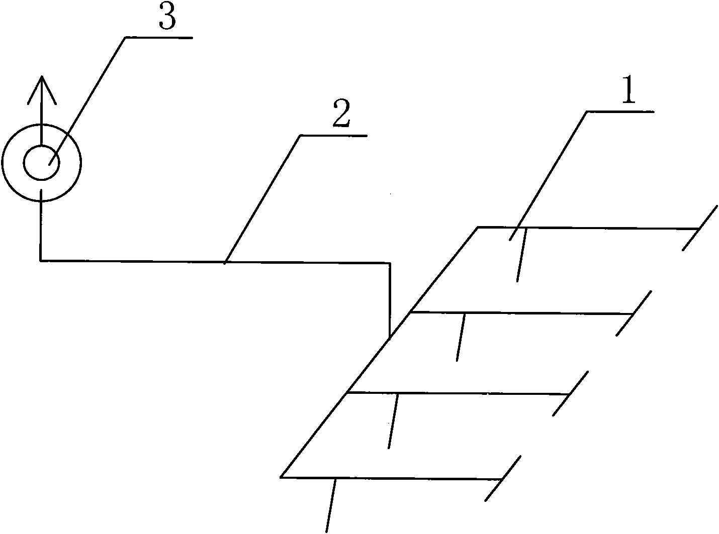
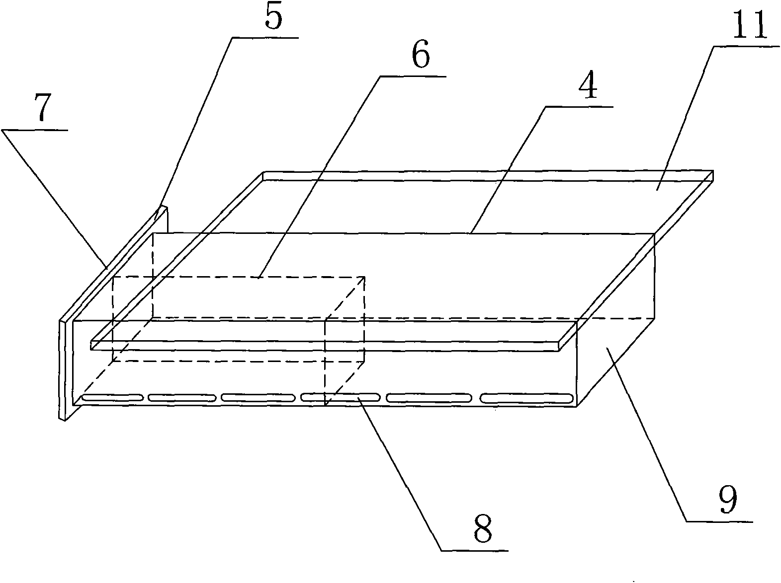
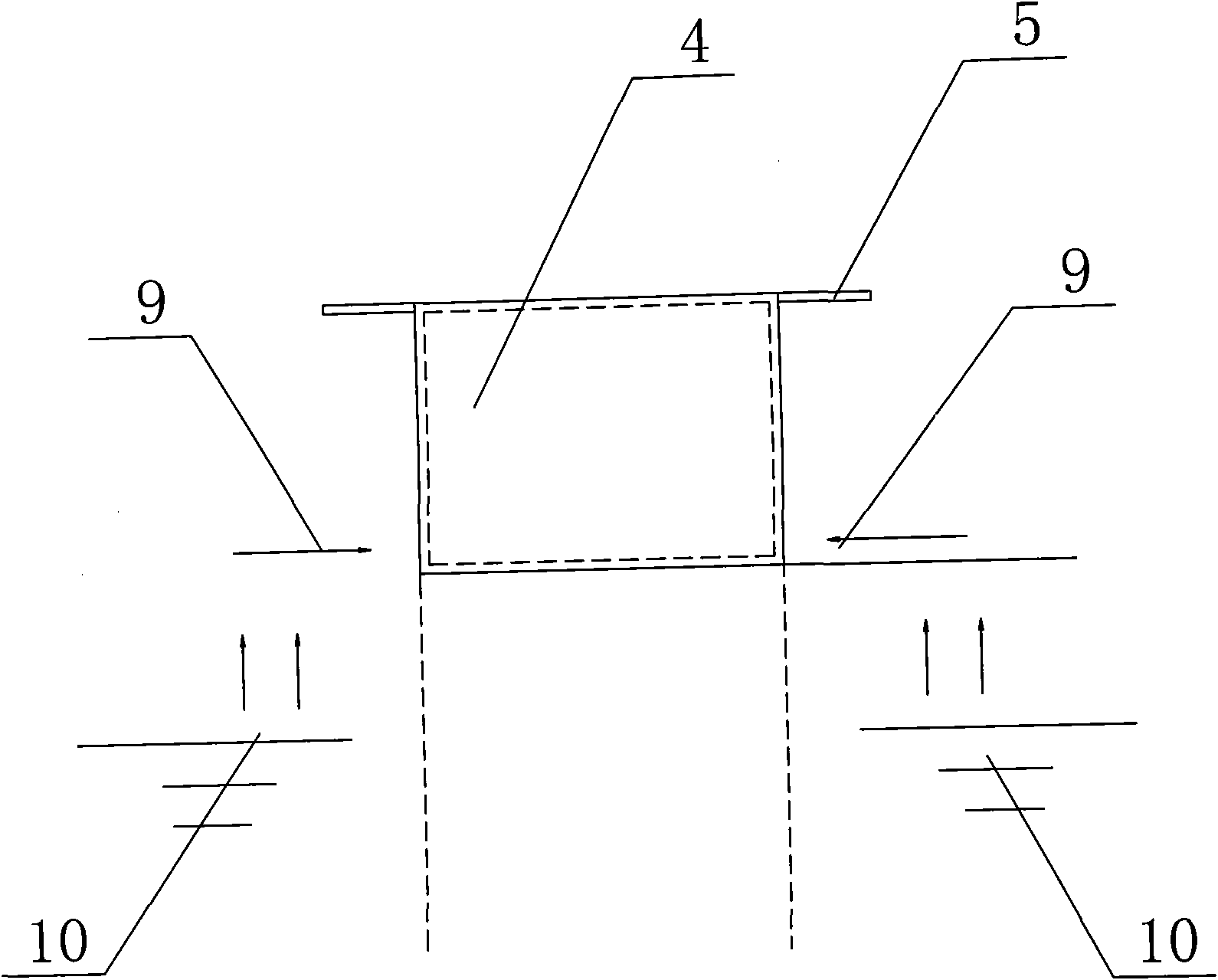
[0015] see Figure 1 to Figure 3 As shown, in this embodiment, an air extraction device for electroplating equipment, which is assembled on the electroplating tank 10 of the electroplating equipment, includes an air extraction hood 1, a fan 3 and an air extraction main branch pipe 2 connected between the two. The main exhaust branch pipe 2 is connected to the fan 3 in an upward slope, which avoids the accumulation of cooling water in the exhaust main branch pipe 2 and affects the occurrence of the ventilation effect. The pipe 4 is provided with an air outlet 7 and an air inlet 9, and the air outlet 7 of the exhaust pipe 4 extends to both sides with auxiliary flow restricting plates 5. The auxiliary flow restricting plate 5 does not affect the entry and exit of the electroplating workpiece. , which can effectively prevent the exhaust gas in the electroplating tank 10 from emitting to the outside, and the air exhaust pipe 4 is provided with a deflector 6, and the deflector 6 and...


PUM


Abstract

The invention discloses an air extracting device for electroplating equipment. The air extracting device is assembled on an electroplating bath of the electroplating equipment and comprises an air extracting cap, a fan and a main air extracting branch pipe connected between the air extracting cap and the fan, wherein the main air extracting branch pipe is connected with the fan in a slope form; the air extracting cap comprises an air extracting pipe; auxiliary current limiting plates extend from the air outlet end of the air extracting pipe towards both sides; a flow guide plate is arranged inside the air outlet end of the air extracting pipe; the side wall of the air extracting pipe is provided with a plurality of elliptical air extracting bar apertures; and the total sectional area of the air extracting bar apertures is equal to the sectional area of the air extracting pipe. The main air extracting branch pipe of the air extracting device for the electroplating equipment is connected with the air extracting cap in the slope form, so that the influence of the accumulation of cooling water in the main air extracting branch pipe on the air extracting effect is eliminated; and the air outlet of the air extracting pipe is provided with the auxiliary current limiting plates, so that the dissipation of waste gas in the electroplating bath can be prevented effectively and the waste gas can be extracted rapidly. The air extracting device has a simple structure, is easy to implement, has good air extracting effect and saves cost.

Description

technical field [0001] The invention relates to an auxiliary production equipment for electroplating lines, in particular to a high-efficiency air extraction device for electroplating equipment. Background technique [0002] As we all know, harmful gases will be generated in electroplating production, and the harmful gases must be exhausted and purified before they can be discharged to meet the requirements of clean production. In the form of exhaust air, the exhaust air volume of the plating tank is considered from a single point of view. If the exhaust effect is to be improved, it is necessary to consider the exhaust air volume too much. Generally, an excessively large fan is used for exhaust air, which not only consumes a lot of power resources, but also increases the The cost of electroplating, and the connection between the exhaust hood and the exhaust main branch pipe is mostly a downslope connection, so the cooling water in the exhaust main branch pipe is easy to accu...

Claims


Application Information

Patent Timeline
Patent Type & Authority Applications(China)
IPC IPC(8): C25D21/04
Inventor 匡岳良胡城纲匡倩茹潘志伟查玉峰曾子豪
Owner 无锡出新环保设备有限公司
Why Eureka
Try Eureka