Signal distribution circuit, signal distribution device, and display device

a signal distribution circuit and signal technology, applied in the direction of static indicating devices, instruments, pulse techniques, etc., can solve the problems of poor yield and defects, low yield, and increase in the number of source drivers, so as to prevent the generation of etching residues, easy to form supply lines, and constant thickness

Active Publication Date: 2013-02-14
SHARP KK
View PDF3 Cites 27 Cited by
  • Summary
  • Abstract
  • Description
  • Claims
  • Application Information

AI Technical Summary

Benefits of technology

[0068]A signal distribution device in accordance with the present invention, as described in the foregoing, includes: supply lines for supplying an input signal to switching elements in a signal distribution circuit; and distribution lines for distributing the input signal to output terminals via the switching elements. The corresponding one of the supply lines and at least one of the distribution lines each have an extension section which extends in an extending direction of one of control lines to which a selection signal for switching on/off the switching elements is applied. Each extension section is formed at positions which do not over

Problems solved by technology

Use of a plurality of source drivers entails various problems including the following ones: (1) The bonding steps to attach the source drivers increase in number, and productivity falls.
(2) Poor yie

Method used


Image

  • Signal distribution circuit, signal distribution device, and display device
  • Signal distribution circuit, signal distribution device, and display device
  • Signal distribution circuit, signal distribution device, and display device

Examples


embodiment 1

[0095]The following will describe an embodiment of the present invention in reference to drawings. The dimensions, materials, shapes, relative positions, etc. of components described in Embodiment 1 are only illustrative and are not intended to limit the scope of the invention unless otherwise indicated.

(Basic Arrangement of Display Device and Signal Distribution Device)

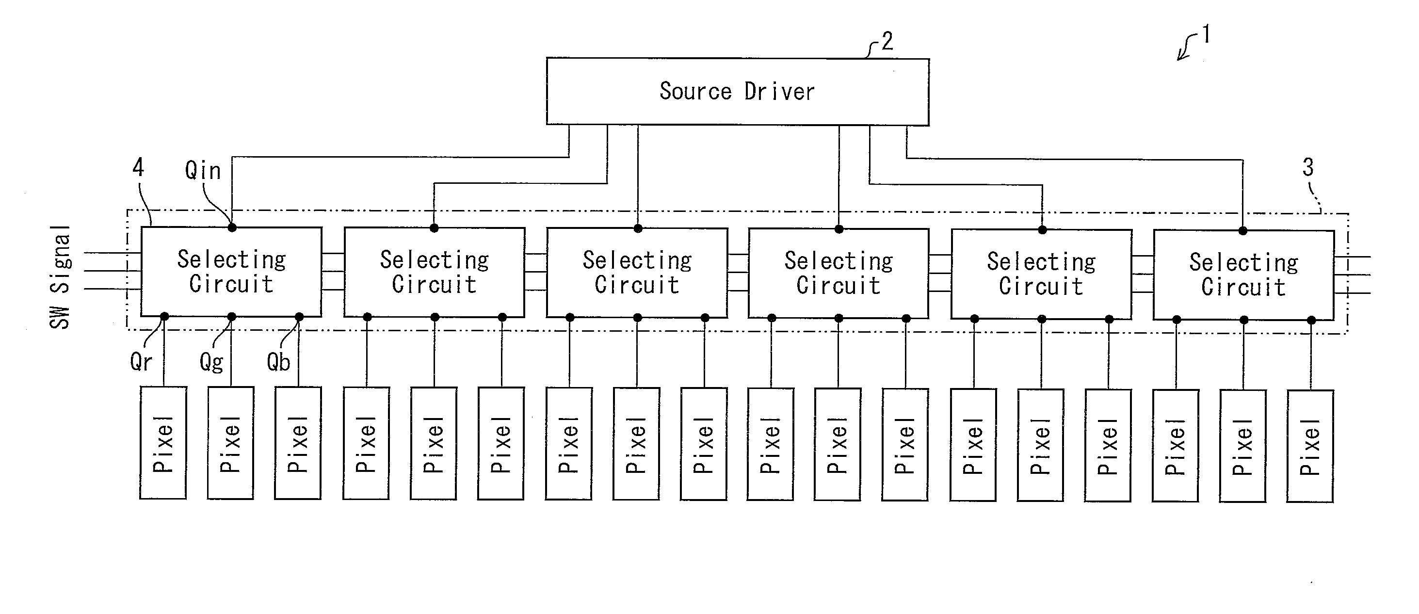
[0096]A display device 1 of Embodiment 1 has a basic arrangement similar to that of the display device 51 described above in reference to FIG. 21. The display device 1 is provided with: a display panel 56 including a display area where a pixel matrix section 55 is provided and a peripheral area; and a signal distribution device 3 (detailed later) which is formed monolithically in the peripheral area. The signal distribution device 3 corresponds to the signal distribution device 54.

[0097]FIG. 4 is a block diagram of a display device 1, more schematically showing the arrangement in FIG. 21. As illustrated in FIG. 4, th...

embodiment 2

[0174]The following will describe another embodiment of the present invention in reference to drawings. The dimensions, materials, shapes, relative positions, etc. of components described in Embodiment 2 are only illustrative and are not intended to limit the scope of the invention unless otherwise indicated. For convenience, members of Embodiment 2 that have the same arrangement as members of Embodiment 1 are indicated by the same reference numerals / symbols and description thereof is omitted.

(Wiring Structure 1 of Signal Distribution Device)

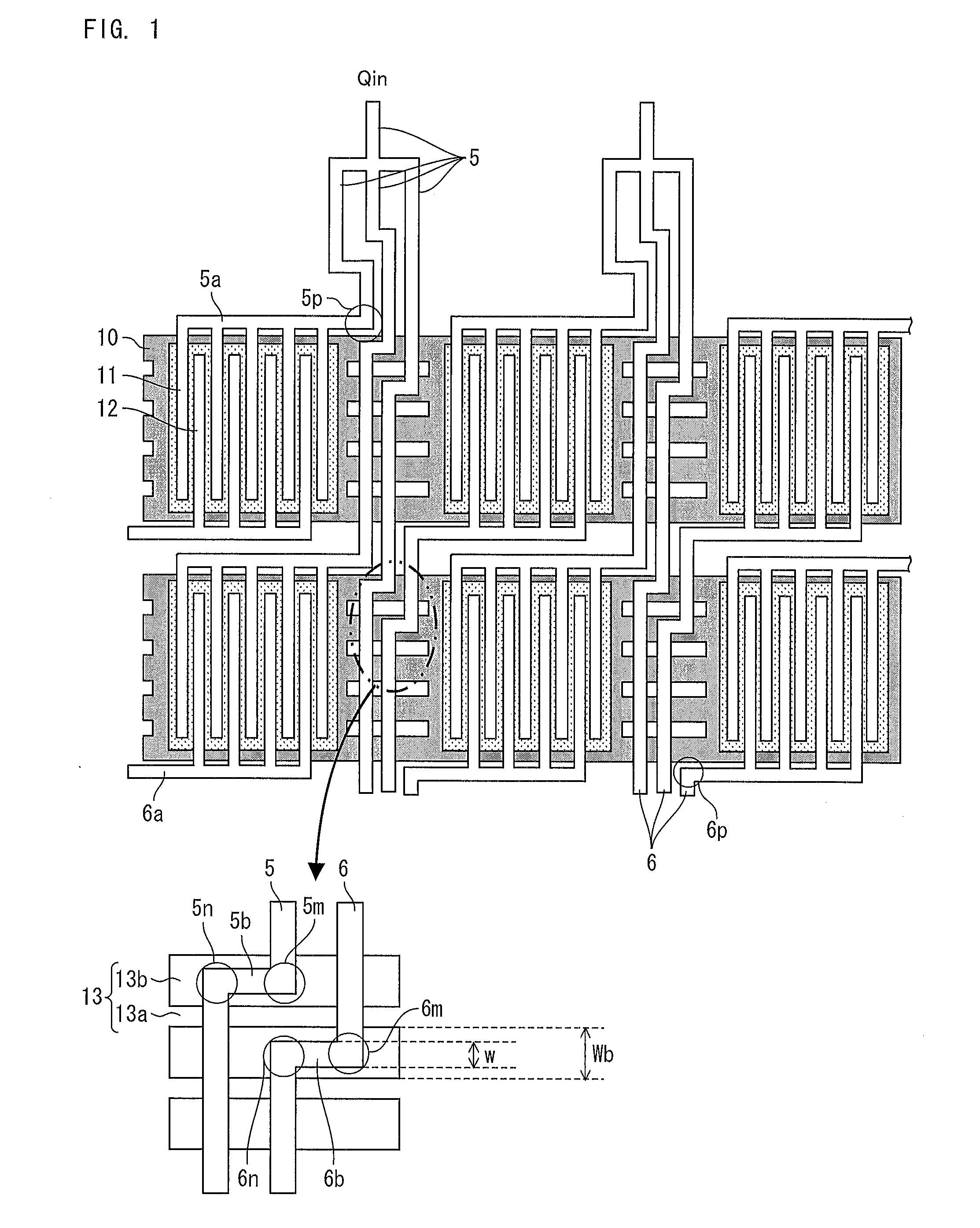
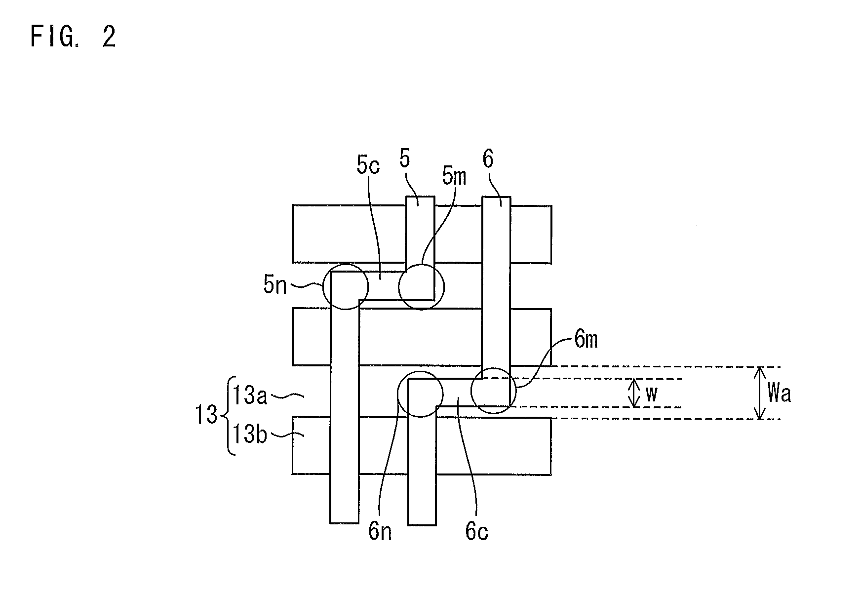
[0175]FIG. 13 is an illustration of a wiring structure for a selecting circuit 4 in a signal distribution device 3 (FIG. 4) in accordance with Embodiment 2. A line arrangement from an input terminal Qin to distribution lines 6 and output terminals Qout via a supply line 5 and a TFT-Mr, a TFT-Mg, and a TFT-Mb each provided with a drain electrode 11 and a source electrode 12 is basically identical to the line arrangement described in Embodiment 1....


PUM


Abstract

Disclosed is a signal distribution device which is provided with: supply lines (5) for supplying input signals to switching elements in signal distribution circuits; and distribution lines (6) for distributing the input signals to output terminals via the switching elements. The corresponding one of the supply lines (5) and at least one of the distribution lines (6) each have an extension section (5a) and an extension section (5b) which extend in an extending direction of a control line (13). A selection signal for switching on/off the associated switching element is applied to the control line (13). The extension sections (5a and 5b) are formed at positions that do not overlap the edge portions of the control line (13) in the extending direction thereof.

Description

TECHNICAL FIELD[0001]The present invention relates to a signal distribution circuit which distributes an input signal to output terminals by time division, a signal distribution device including the signal distribution circuit, and a display device including the signal distribution device.BACKGROUND ART[0002]Various types of liquid crystal displays (LCD's) have been developed as flat display devices. Among them, those based on active matrix technology are popular. A plurality of source drivers are used in many of the devices because the number of signal lines has increased in order to cope with recent increase in pixel number in pixel matrix sections for high definition.[0003]Use of a plurality of source drivers entails various problems including the following ones: (1) The bonding steps to attach the source drivers increase in number, and productivity falls. (2) Poor yields and defects, such as corrosion caused by a difference in electric potential between terminals, are likely to ...

Claims


Application Information

Patent Timeline
IPC IPC(8): G09G3/36
CPCG02F1/13454G09G3/3688G09G2300/0426G02F1/1345H01L29/7869H01L27/124H01L27/1244G09G2310/0297G02F1/133G09G3/36G02F1/1368G02F1/1343
Inventor TAGAWA, AKIRASAKAMOTO, MAYUKOTAKAHASHI, YOSHIHISA
Owner SHARP KK
Why Eureka
Try Eureka