Hydraulic resistance type tall building escape device

A technology for escape devices and high-rise buildings, which is applied in the field of escape devices for high-rise buildings. It can solve the problems that affect the durability and reliability of escape devices, have no safe hiding place, and can only wait for rescue from others. It achieves light weight, small size, compact effect

Inactive Publication Date: 2011-02-16
CHANGAN UNIV
View PDF5 Cites 9 Cited by
  • Summary
  • Abstract
  • Description
  • Claims
  • Application Information

AI Technical Summary

Problems solved by technology

[0002] With the increasing development of social economy, the continuous acceleration of urbanization process and the continuous improvement of people's living standards, there are more and more high-rise buildings such as high-rise commercial buildings, office buildings, and residential buildings, and the floors are built higher and higher. When earthquakes or other disasters cannot escape from stairs or elevators, and there is no safe place to hide, they can only wait for the rescue of others, and sometimes they will be injured by disasters due to the slowness of rescue. Therefore, a safe, reliable, Easy-to-use high-rise self-rescue escape appliance
At present, in the prior art, the vast majority of high-rise escape devices use the principle of friction, that is, the friction between objects is used as the source of resistance of the escape device. Although it can initially solve some problems of high-rise escape, the friction force is difficult. Dynamic adjustments are made according to the whereabouts of the human body, and it is difficult to achieve the stability of the human body when it falls; moreover, there is a close relationship between the friction force and the interacting medium, and the escape device using the friction principle will lose its relative friction surface after repeated use will change, which will seriously affect the durability and reliability of the escape device

Method used


Image

  • Hydraulic resistance type tall building escape device
  • Hydraulic resistance type tall building escape device
  • Hydraulic resistance type tall building escape device

Examples


Embodiment 1

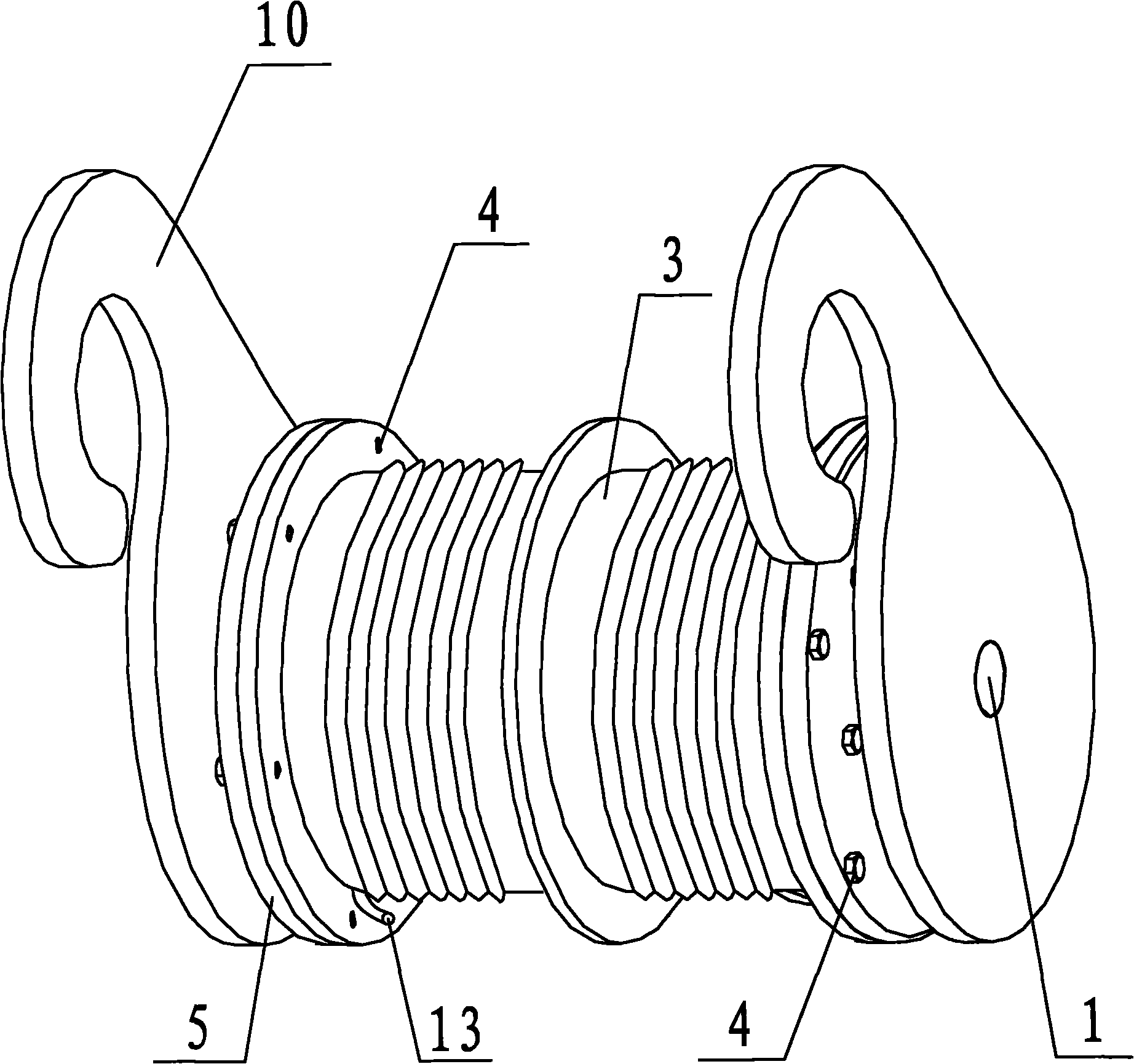
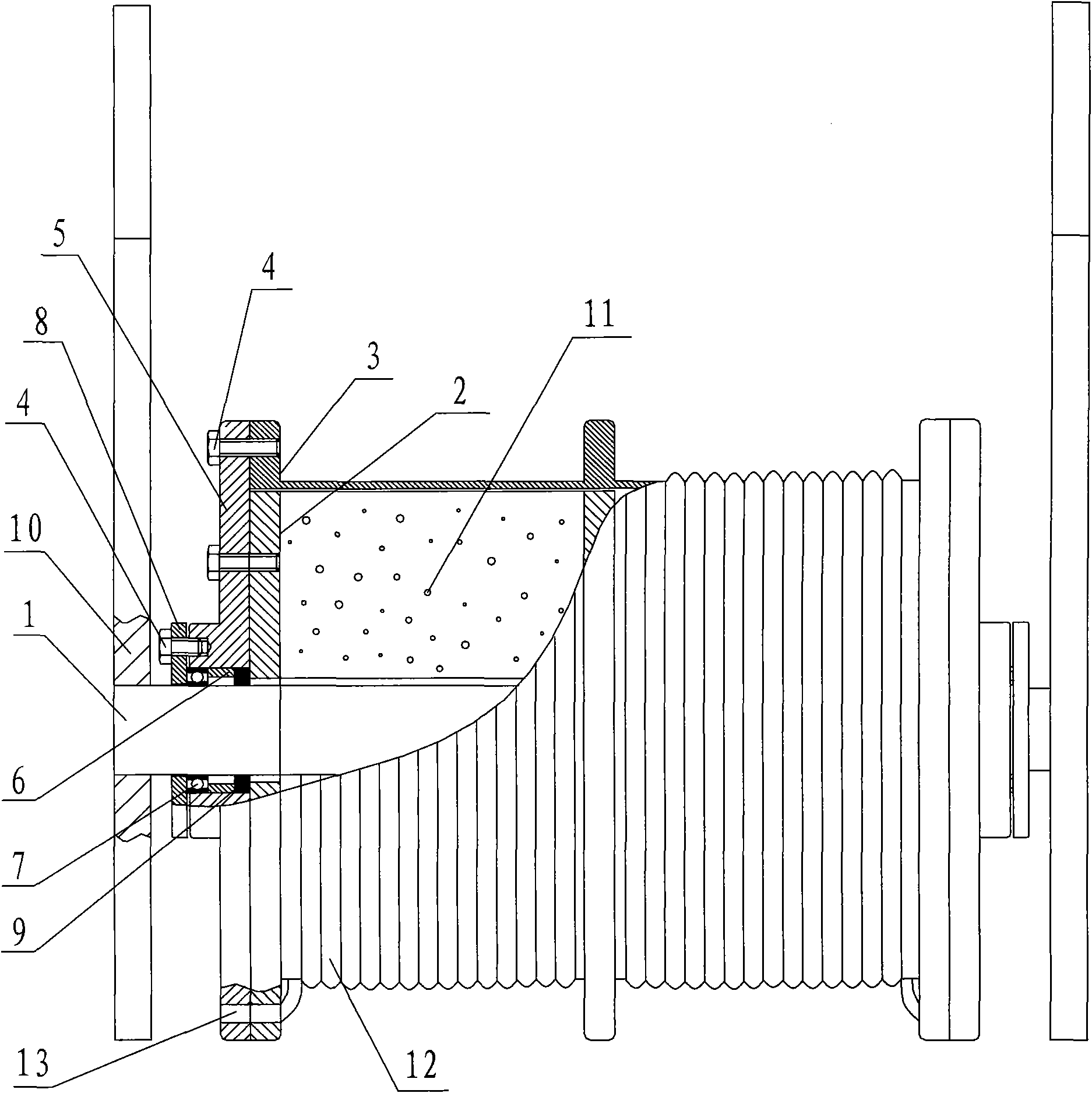
[0035] Such as figure 1 and figure 2 As shown, the present invention includes a rotary shaft 1, a damping rotor 2 sleeved on the rotary shaft 1 and a bobbin 3 sleeved on the damping rotor 2, both ends of the damping rotor 2 and the bobbin 3 are The bolt 4 is fixedly connected with the cover plate 5, the wire rope 12 used for escape is wound on the bobbin 3, and the two ends of the bobbin 3 and the corresponding positions on the cover plate 5 are provided with wire ropes for tying. 12 winding holes 13, the cover plate 5 is set on the rotary shaft 1 through the bushing 6 and the rolling bearing 7 accommodated in the bushing 6, the cover plate 5 is fixedly connected with the end cover 8 through the bolt 4, and the The rotary shaft 1 is provided with a sealing ring 9 for sealing the rotary shaft 1, the bushing 6 and the damping rotor 2, the two ends of the rotary shaft 1 are fixedly connected with hooks 10, the rotary shaft 1, the damping rotor 2, the winding A viscous liquid 1...

Embodiment 2

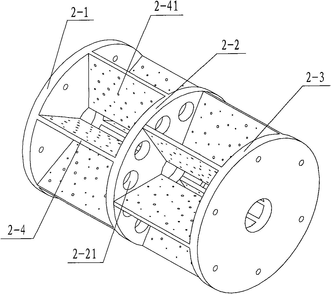
[0040] Such as Figure 4 As shown, the difference between this embodiment and Embodiment 1 is that the blade 2-4 is a helical blade, and the blade 2-4 connected between the annular end plate 2-1 and the middle partition plate 2-2 It is opposite to the spiral direction of the blade 2-4 connected between the middle partition plate 2-2 and the circular end plate 2-3; the through hole 2-21 is triangular. All the other structures are the same as in Example 1. Figure 4 Among them, the blade 2-4 connected between the annular end plate one 2-1 and the intermediate partition plate 2-2 and the blade connected between the intermediate partition plate 2-2 and the annular end plate two 2-3 The number of 2-4 is 6 pieces, and the unmarked circular holes on the annular end plate one 2-1 and the annular end plate two 2-3 are the holes that the bolt 4 needs.

[0041] The working principle and working process of the present invention are: when an emergency occurs, the escapee takes out the li...


PUM


Abstract

The invention discloses a hydraulic resistance type tall building escape device, comprising a revolving axle, a damping rotor sheathed on the revolving axle and a winding reel sheathed on the damping rotor; wherein the two ends of the damping rotor and the two ends of the winding reel are all fixedly connected with a cover plate by virtue of bolts, the winding reel is wound with a steel wire rope used for escaping, the two ends of the winding reel and corresponding position on the cover plate are provided with a winding hole used for tying the steel wire rope, the cover plate is sheathed on the revolving axle by virtue of an axle sleeve and a rolling bearing contained in the axle sleeve, the cover plate is fixedly connected with an end cover by virtue of bolts, the revolving axle is provided with a seal ring used for sealing the revolving axle, the axle sleeve and the damping rotor, the two ends of the revolving axle are fixedly connected with a hook, and a hermitical space formed by the revolving axle, the damping rotor, the winding reel and the seal ring is injected with viscous liquid. The invention has compact structure, novel and reasonable design, operation convenience, high stability, durability and reliability, good cyclic utilization performance, low cost and strong practicability and is beneficial to popularization and application.

Description

technical field [0001] The invention relates to a high-rise escape device, in particular to a liquid resistance type high-rise escape device. Background technique [0002] With the increasing development of social economy, the continuous acceleration of urbanization process and the continuous improvement of people's living standards, there are more and more high-rise buildings such as high-rise commercial buildings, office buildings, and residential buildings, and the floors are built higher and higher. When earthquakes or other disasters cannot escape from stairs or elevators, and there is no safe place to hide, they can only wait for the rescue of others, and sometimes they will be injured by disasters due to the slowness of rescue. Therefore, a safe, reliable, A convenient high-rise self-rescue escape appliance. At present, in the prior art, the vast majority of high-rise escape devices use the principle of friction, that is, the friction between objects is used as the s...

Claims


Application Information

Patent Timeline
Patent Type & Authority Applications(China)
IPC IPC(8): A62B1/12
Inventor 张志峰侯有良周力曹婷
Owner CHANGAN UNIV
Why Eureka
Try Eureka