
Brake mechanism of escape backpack slow descending device

A brake mechanism and slow-down technology, applied in the field of escape backpacks, can solve the problems of high cost, troublesome installation and maintenance, complex structure of reset parts, etc., and achieve the effect of not easy to install, convenient and fast to install

Pending Publication Date: 2020-02-04
平湖市家安消防科技股份有限公司
View PDF0 Cites 1 Cited by
  • Summary
  • Abstract
  • Description
  • Claims
  • Application Information

AI Technical Summary

Problems solved by technology

[0007] The brake mechanism in the prior art adopts the centrifugal method, through the high-speed rotation, the brake pads are subjected to centrifugal force away from the center and contact with the outer brake disc to achieve the purpose of deceleration, and at the same time, the brake pads move toward the center through the tension spring or the reset member , so that there is a gap between the brake pad and the brake disc when the speed is slow, all of them need to use a reset member (tension spring) with a relatively complicated structure. For example, during installation, the brake pad is installed after the brake disc and the bump For installation, if the brake pads are installed first, the two ends of the extension spring cannot be hooked on the two brake pads. At this time, the two brake pads must be connected through the extension spring first, and then put together into the accommodation groove formed by the protrusions. Inside, it takes a lot of effort to separate the two brake pads by a certain distance (this distance must ensure that the brake pads can be placed neither too large nor too small), and the space for installing the brake pads is small. It is difficult for the staff to control this distance, and the installation and maintenance are more troublesome

Method used


Image

  • Brake mechanism of escape backpack slow descending device
  • Brake mechanism of escape backpack slow descending device
  • Brake mechanism of escape backpack slow descending device

Examples


Embodiment Construction

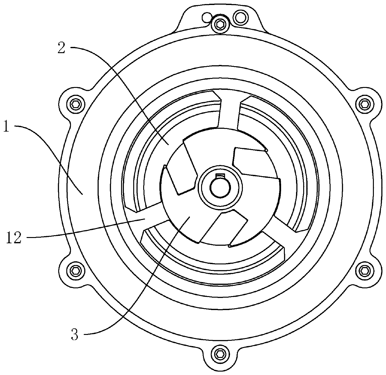
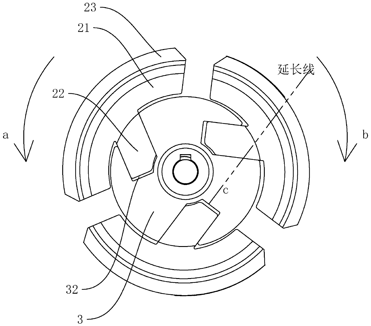
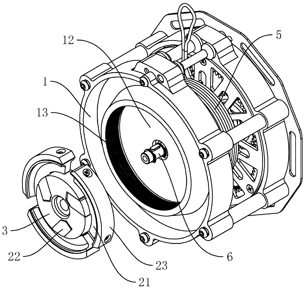
[0025] refer to Figure 1 to Figure 5 The embodiment of the braking mechanism of the escape backpack slow-down device of the present invention will be further described.

[0026] In the description of the present invention, it should be noted that for orientation words, such as the term "center", "horizontal (X)", "longitudinal (Y)", "vertical (Z)", "length", " Width", "Thickness", "Top", "Bottom", "Front", "Back", "Left", "Right", "Vertical", "Horizontal", "Top", "Bottom", "Inner ", "outside", "clockwise", "counterclockwise" and other indication orientations and positional relationships are based on the orientation or positional relationship shown in the drawings, and are only for the convenience of describing the present invention and simplifying the description, rather than indicating or implying the Means that a device or element must have a specific orientation, be constructed and operated in a specific orientation should not be construed as limiting the specific protect...


PUM


Abstract

The invention discloses a brake mechanism of an escape backpack slow descending device. The brake mechanism comprises a brake cover plate and a brake shell with a containing groove, and further comprises a rotating block located in the containing groove and connected with a brake shaft, and at least three brake blocks. At least three strip-shaped eccentric grooves are formed in the rotating blockand evenly distributed circumferentially. The eccentric grooves extend inwards from the outer circumference of the rotating block. The extension cords of the eccentric grooves do not penetrate throughthe center of the rotating block. The brake blocks are evenly distributed circumferentially. Each brake block comprises a brake pad and an eccentric block, wherein the brake pad is in an arc shape, the shape of the eccentric block is the same as that of the corresponding eccentric groove, and the eccentric block extends into the corresponding eccentric groove and is slidingly connected with the eccentric groove. A reset piece for making the brake blocks to reset is omitted, meanwhile the aim of speed reduction through eccentric friction brake shells of the brake pads in use can be ensured, the installing efficiency is improved, and the brake blocks can be conveniently detached during maintaining.

Description

technical field [0001] The invention belongs to the field of escape knapsacks, and more specifically relates to a brake mechanism of a slow-down device for an escape knapsack. Background technique [0002] At present, the pace of urbanization is getting faster and faster, and the tension of urban land has led to more and more high-rise buildings. When disasters such as fires occur on high floors, people have limited ways to evacuate the accident site, and the risk factor is high. In this context, high-floor slow descent escape equipment was born. [0003] For example, the Chinese patent with application number 2017107668188 discloses a high-rise escape backpack, which includes an escape device, and the escape device includes a box, a drum, a main shaft, and a transmission, wherein the drum is installed on the main shaft, and the An escape rope is connected, one end of the main shaft is pivotally arranged on the left side plate of the box, the other end of the main shaft is ...

Claims


Application Information

Patent Timeline
Patent Type & Authority Applications(China)
IPC IPC(8): A62B1/14
CPCA62B1/14
Inventor 王跃
Owner 平湖市家安消防科技股份有限公司
Learn More