Oil saving stepless speed variator

A technology of continuously variable transmission and sliding disc, which is applied to belts/chains/gears, mechanical equipment, transmission devices, etc., and can solve problems such as large noise, large exhaust emissions, and incomplete transmission of payloads

Inactive Publication Date: 2006-08-30
李光华
View PDF0 Cites 1 Cited by
  • Summary
  • Abstract
  • Description
  • Claims
  • Application Information

AI Technical Summary

Problems solved by technology

Therefore, the motorcycle speed change is mainly to use the centrifugal force generated by the centrifugal beads in the active transmission disc to push the sliding plate of the active transmission disc to squeeze the transmission belt, changing the rotation diameter of the transmission belt, so as to realize the large wheel with a small wheel or the small wheel with a large wheel. The purpose of the wheel is to change the speed, but when accelerating, the centrifugal force generated by the centrifugal beads has the problem of instability and high consumption, so that the payload of the engine is not fully transmitted to the driving wheel, so that the drive cannot get the effective power of the power. , when the engine works under light load, the fuel consumption is high, the wear is large, the exhaust emission is large, and the noise is large

Method used


Image

  • Oil saving stepless speed variator
  • Oil saving stepless speed variator
  • Oil saving stepless speed variator

Examples


Embodiment Construction

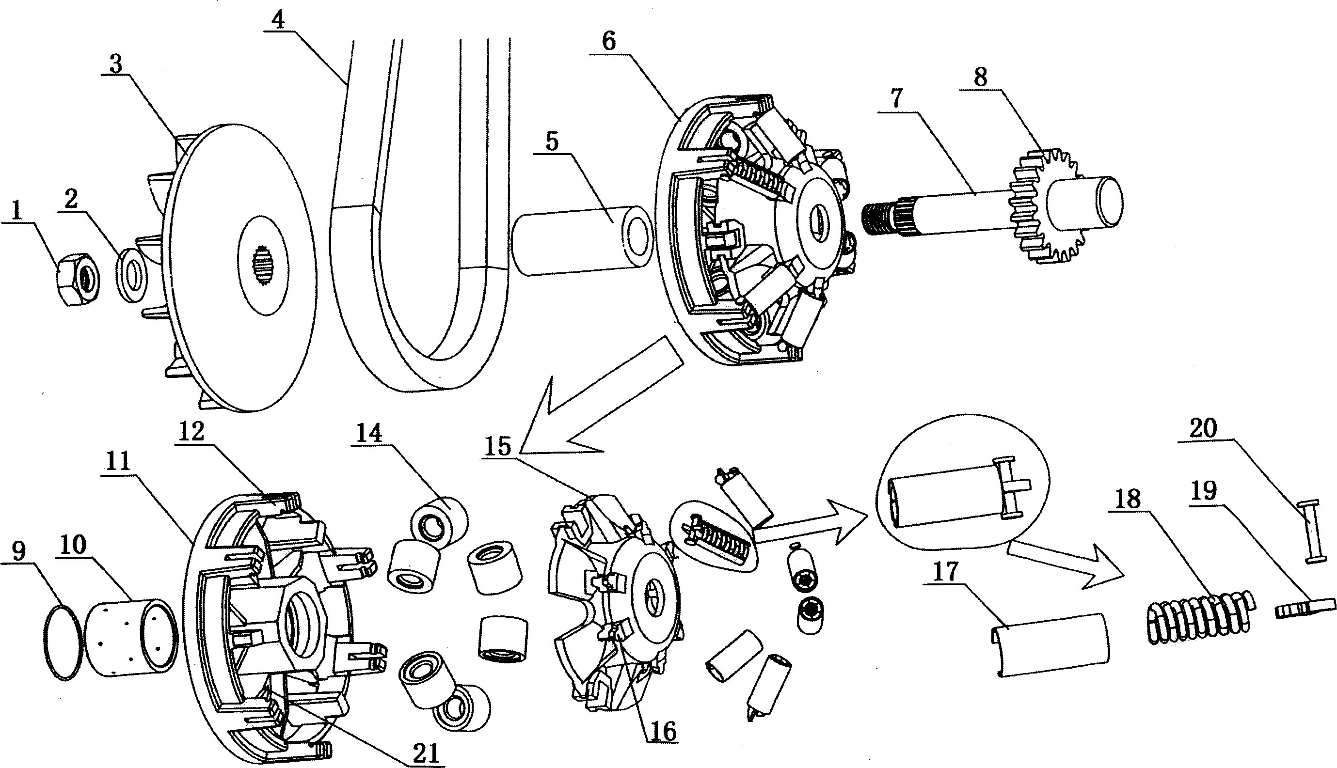
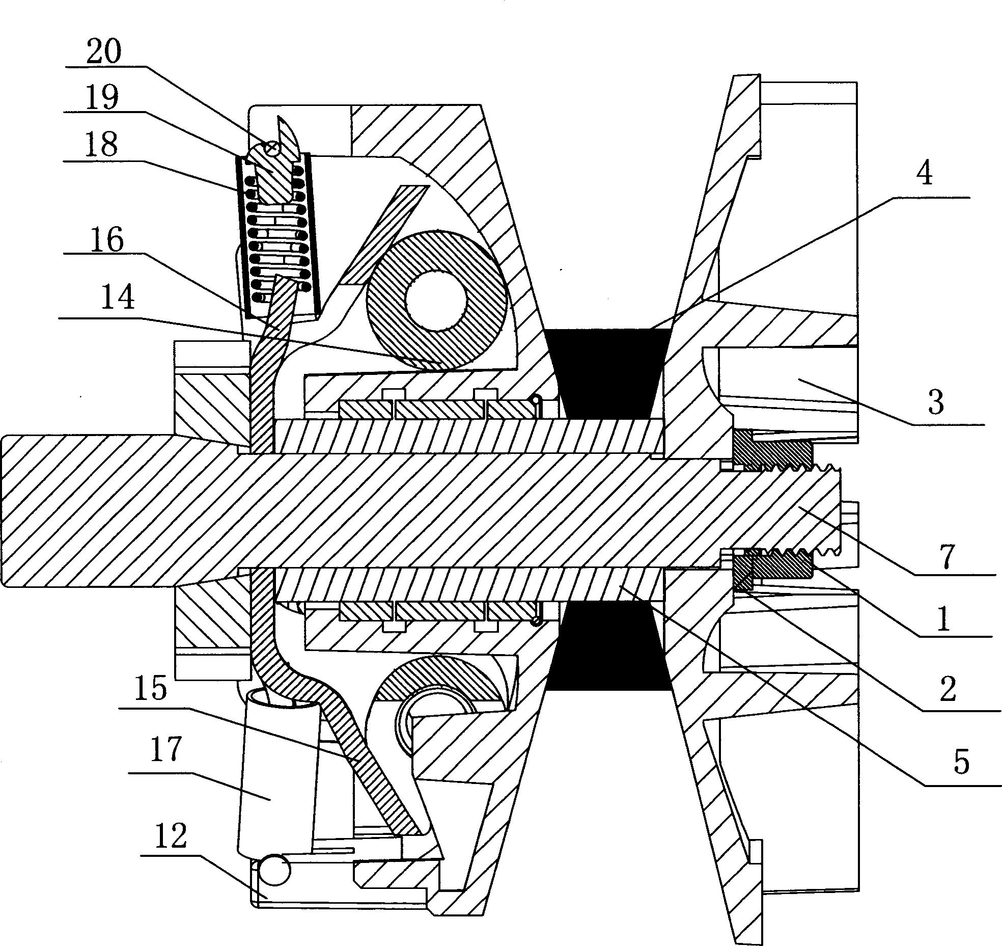
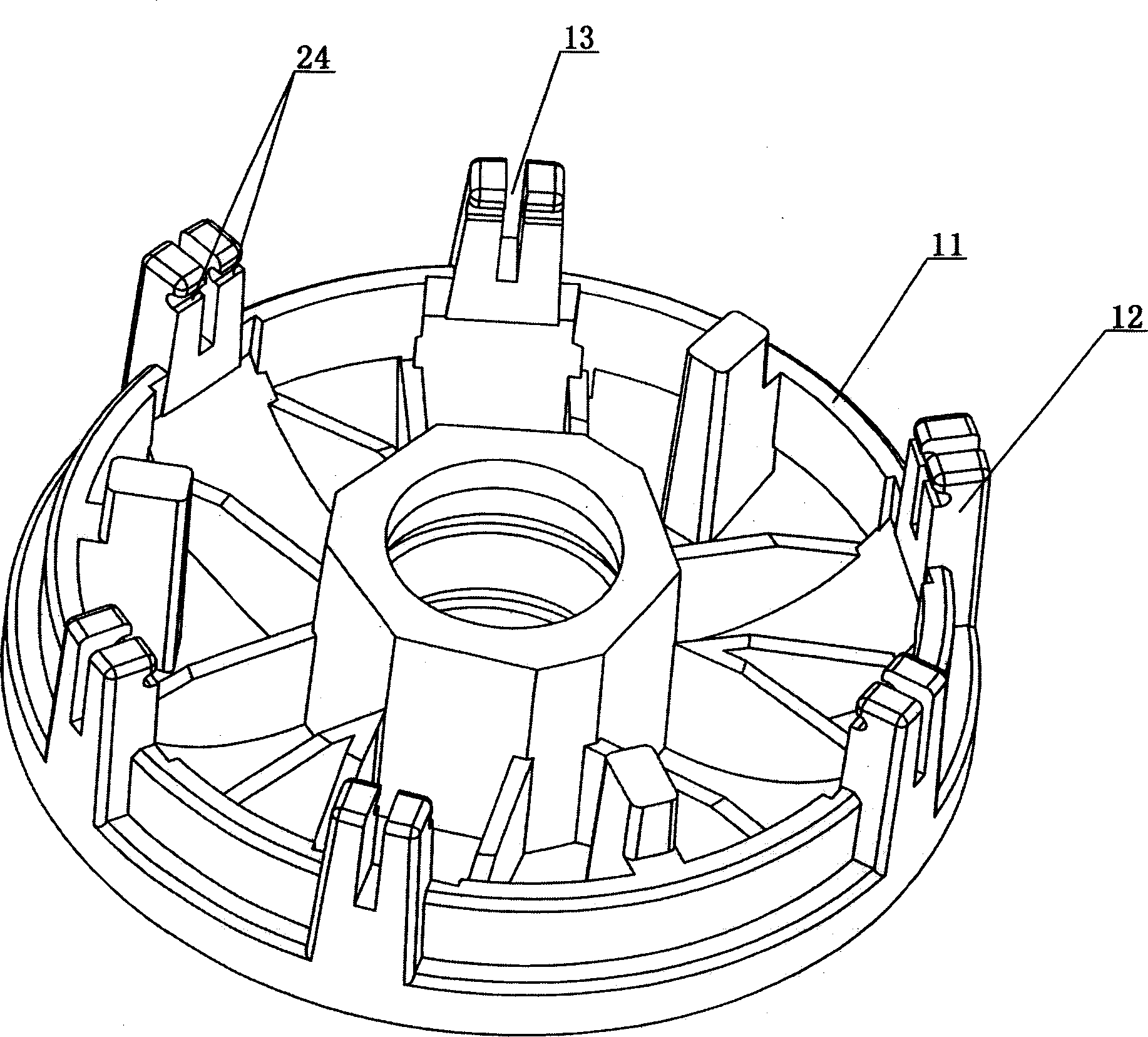
[0011] Below with reference to accompanying drawing, the present invention will be further described: as figure 1 As shown, the fuel-saving continuously variable transmission includes the active sliding disc assembly 6, the main shaft 7, the starting gear 8, the active shifting sliding disc 11, the centrifugal bead 14, the centrifugal bead cover 15 and the track groove 21 in the centrifugal bead cover 15 ; Fan blade disc 3, variable speed belt 4, fixed steel sleeve 5, wear-resistant sleeve washer 9, wear-resistant sleeve 10, active variable speed sliding disc 11, centrifugal bead cover 15 are set on the main shaft 7 in sequence, and the main shaft nut 1 and The gasket 2 is tightened, and the main shaft 7 is provided with a starting gear 8; the centrifugal ball 14 is located in the track groove 21 in the active transmission sliding disc 11, and the transmission belt 4 is sleeved between the blade disc 3 and the active sliding disc assembly 6. on spindle 7, as figure 2 , ima...


PUM


Abstract

The invention relates to a fuel-saving buncher, in which a spring-supporting column is disposed on the cylindrical end face along the driving variable-speed sliding disk. A spring setting angle is disposed on the centrifugal ball block cover. One end of a secondary variable-speed spring is set on the spring setting angle, and the other end is disposed on the spring moving arm mounted on the spring-supporting column. A spring shield sleeve is disposed on the secondary variable-speed spring. On the spring-supporting column are opened longitudinal and horizontal grooves and on the spring moving arm are disposed lugs and grooves.

Description

Technical field: [0001] The invention relates to a continuously variable transmission, specifically a continuously variable transmission mainly used for motorcycles. Background technique: [0002] The existing continuously variable speed motorcycles have fast wear and tear of parts, high noise and large exhaust emissions. The reason is that the clutch used by the motorcycle is a centrifugal clutch. The engine spins together. On road sections where the speed should not be too fast, such as streets and alleys, bustling areas, obstacle roads, etc., it is difficult to give full play to the economical speed of motorcycles. When the motorcycle changes from low speed to high speed, the driving wheels cannot get the effective power of the engine power; when the motorcycle is working under light load conditions, the speed change method is that the engine shaft drives the active transmission disc assembly to rotate, and the active transmission disc track The centrifugal beads in the...

Claims


Application Information

Patent Timeline
IPC IPC(8): F16H9/12
Inventor 李光华
Owner 李光华
Why Eureka
Try Eureka