
High-altitude rescue device and using method thereof

A high-altitude, sealed shell technology, applied in life-saving equipment, building rescue, etc., can solve the problems of rescue risks, difficulty in achieving stability, etc., and achieve the effects of improving safety, facilitating promotion and use, and compact structure

Inactive Publication Date: 2021-06-04
XIAN HISUN ELECTRICAL AUTOMATION TECH
View PDF0 Cites 1 Cited by
  • Summary
  • Abstract
  • Description
  • Claims
  • Application Information

AI Technical Summary

Problems solved by technology

[0002] With the rapid development of urbanization in the country, there are many high-rise buildings, 30 to 40-story high-rise buildings can be found everywhere, especially in big cities, there are more and more skyscrapers, and the fire hazards of high-rise buildings increase accordingly. Once a fire breaks out, the fire-fighting aerial ladder or the large-scale fire-fighting aerial ladder is difficult to meet its fire-fighting and the needs of helping people escape from heights. In the prior art, most high-rise rescue and escape devices use the friction principle, that is, use the friction between objects As the source of resistance of the escape device, friction force can initially solve some problems of high-rise escape, but it is difficult to dynamically adjust the friction force according to the falling situation of the human body, and it is difficult to achieve the stability of the fall. Someone proposed to use the damper design High-rise escape device, but considering the complexity of the rescue environment, the objects to be rescued include objects and people. When encountering a heavy rescue object, if the resistance of the damper is single and the resistance is not enough, it will cause certain risks to the rescue.

Method used


Image

  • High-altitude rescue device and using method thereof
  • High-altitude rescue device and using method thereof

Examples


Embodiment Construction

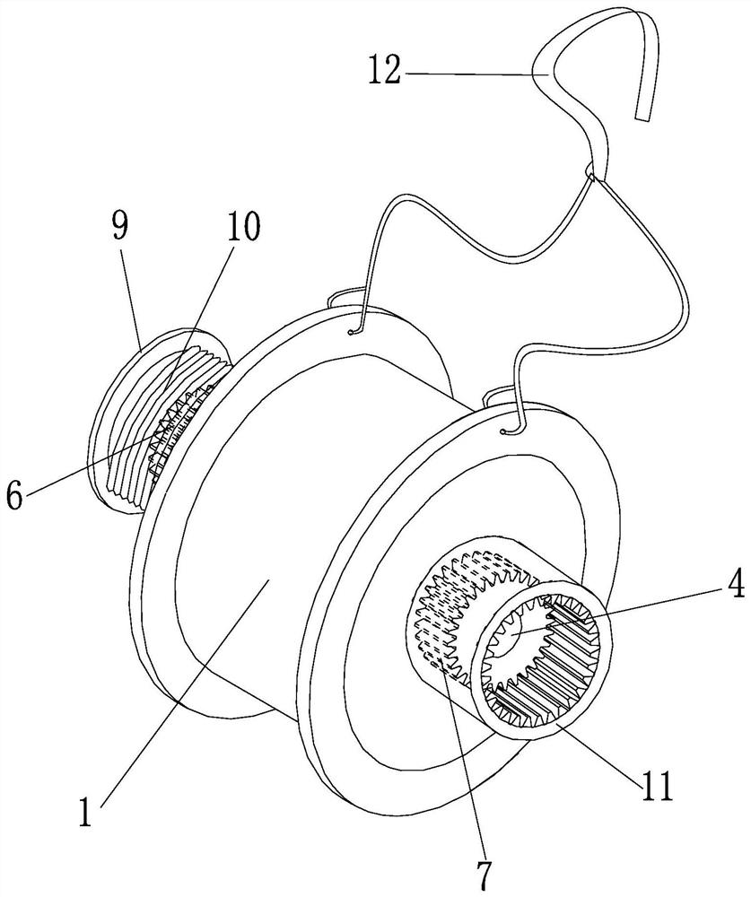
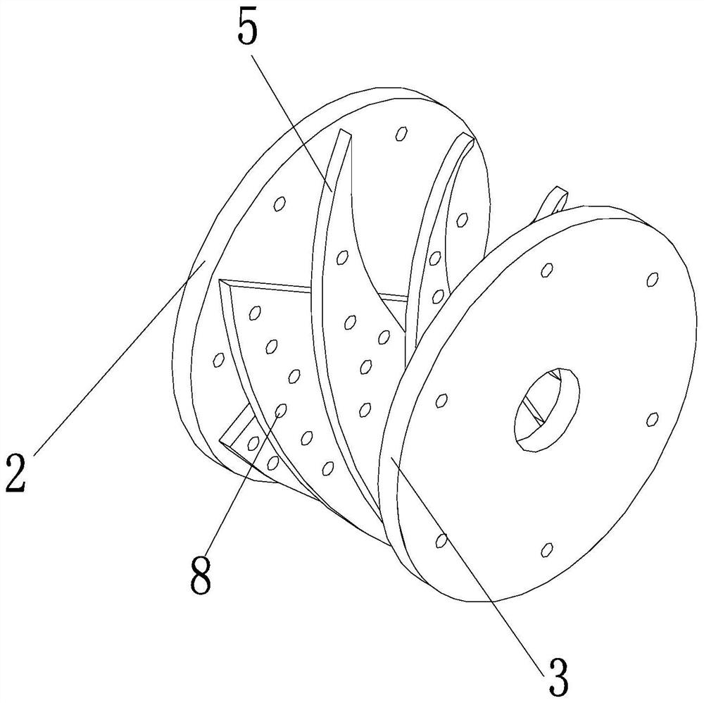
[0028] Such as figure 1 with figure 2 As shown, the high-altitude rescue apparatus of the present invention includes a sealing housing 1 and a damping liquid filled in the sealing housing 1, and a damping rotating assembly disposed within the sealing housing 1; the damping rotating assembly includes uniform and sealing The first end plate 2 and the second end plate 3 of the housing 1 are fixedly connected, and the active connection between the first end plate 2 and the second end plate 3 is provided with a plurality of The blade 5 is provided with a plurality of damping holes 8 on the blade 5, and one end of the rotation shaft 4 extends the first end plate 2, and the first end plate 2 is installed on one segment of the first end plate 2. The gear 6 is mounted on the first gear 6, and the wire barrel 9 is wound around the high-rise, and the other end of the rotating shaft 4 extends the second end plate 3. Further, the second gear 7 is mounted on a section of the rotating shaft 4 pr...


PUM


Abstract

The invention discloses a high-altitude rescue device and a using method thereof. The high-altitude rescue device comprises a sealing housing and damping liquid as well as a damping rotating assembly arranged in the sealing housing, wherein the damping rotating assembly comprises a first end plate, a second end plate and a rotating shaft; a plurality of blades are arranged on the rotating shaft; a plurality of damping holes are formed in the blades; one end of the rotating shaft extends out of the first end plate; a first gear is mounted on one section, extending out of the first end plate, of the rotating shaft; a wire winding barrel is mounted on the first gear; a steel wire rope for high-altitude escape is wound on the wire winding barrel; the other end of the rotating shaft extends out of the second end plate; a second gear is mounted on one section, extending out of the second end plate, of the rotating shaft; a gear ring which corresponds to the second gear in structure is arranged on the second gear; and a hanger is arranged on the sealing housing. The device is simple in structure, reasonable in design, convenient to realize, can be effectively applied to high-rise building rescue, is simple to operate, is convenient to cascade, is good in using effect, and is convenient to popularize and use.

Description

Technical field [0001] The invention belongs to the technical field of rescue equipment, and is specifically involved in a height rescue device and a method of use. Background technique [0002] With the rapid development of the national urbanization, high-rise forest, three or forty-storey high-rise buildings, especially in large cities, more and more skyscrapers, the fire hazards of high-rise buildings have increased, and there is a fire Once a fire, the fire-fighting ladder is difficult or large fireless ladder is difficult to meet its fire protection, helping people from escape, and in the prior art, the vast majority of high-rise rescue escape unit uses friction principles, that is, the object is used The friction is the source of the escape. Although some problems can be initially solved, the friction is difficult to dynamically adjust according to the loss of the human body, and it is difficult to achieve the stability of the drop, some people have proposed the design of t...

Claims


Application Information

Patent Timeline
Patent Type & Authority Applications(China)
IPC IPC(8): A62B1/06A62B1/18
CPCA62B1/06A62B1/18
Inventor 不公告发明人
Owner XIAN HISUN ELECTRICAL AUTOMATION TECH
Learn More