Multifunctional friction welding table

A multifunctional, friction welding technology, applied in welding equipment, non-electric welding equipment, metal processing equipment, etc., can solve problems such as low work efficiency

Inactive Publication Date: 2012-06-27
NORTHWESTERN POLYTECHNICAL UNIV
View PDF0 Cites 0 Cited by
  • Summary
  • Abstract
  • Description
  • Claims
  • Application Information

AI Technical Summary

Problems solved by technology

[0004] In order to overcome the problem of low work efficiency caused by the inability of different friction welding methods to be welded by the existing friction welding machine on one machine, the present invention provides a multifunctional friction welding table

Method used


Image

  • Multifunctional friction welding table
  • Multifunctional friction welding table
  • Multifunctional friction welding table

Examples


Embodiment 1

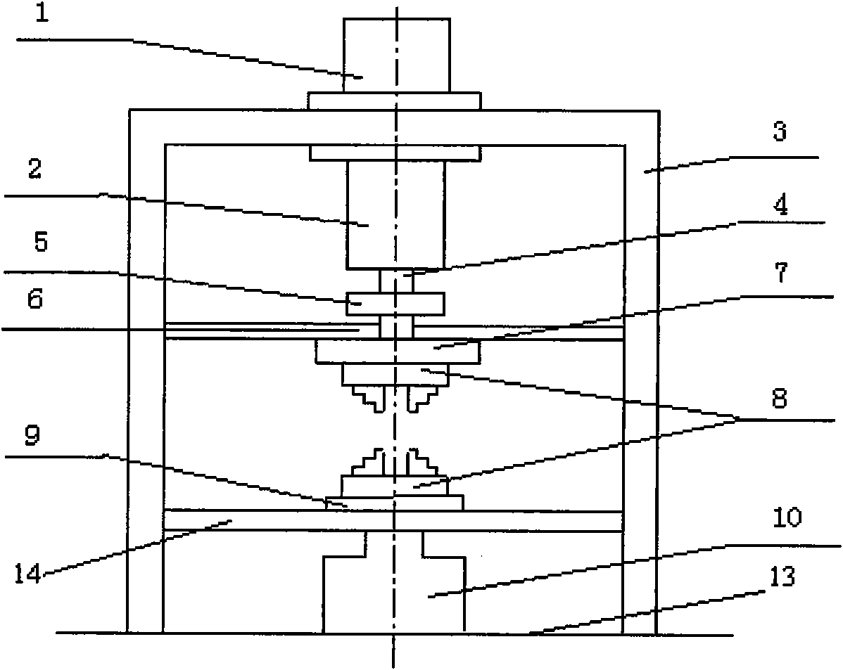
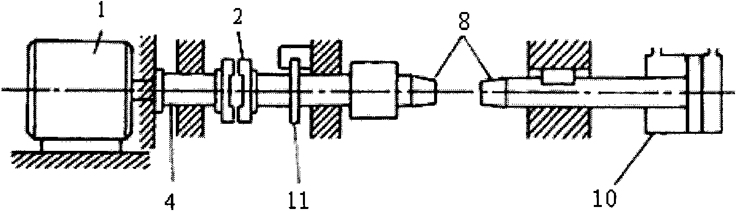
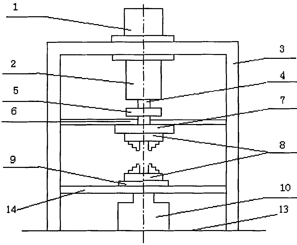
[0013] Embodiment 1: A multifunctional friction welding table, including a motor 1, a clutch brake combination 2, a gantry frame 3, a main shaft 4, a coupling 5, a first partition 6, a flywheel disc 7, and a weldment clamping end 8. Workbench 9, hydraulic system 10, bottom plate 13 and second partition 14. The entire multifunctional friction welding table is fixed on the gantry 3, the first partition 6 and the second partition 14 are fixedly connected to the brackets on both sides of the gantry 3, and the motor 1 is located on the top of the gantry 3 and placed perpendicular to the ground , The motor shaft faces downward, the flywheel disc 7 is under the first partition 6, one end of the coupling 5 passes through the first partition 6 and is fixed on the upper surface of the flywheel disc 7, and the lower surface of the flywheel disc 7 is fixedly connected to the weldment The upper end of the clamping end 8 and the other end of the coupling 5 are fixedly connected to the main ...

Embodiment 2

[0014] Embodiment 2: Realize continuous drive friction welding on a multifunctional friction welding table. The workpieces to be welded are respectively held on the weldment clamping ends 8 at the upper and lower ends, the motor 1 is turned on, and the motor spindle 4 is driven to rotate and accelerate to a predetermined speed. The horizontal workbench 9 of the transmission rises, so that the two workpieces move toward each other, the end faces are contacted and plasticized under the action of friction, the clutch and brake combination 2 is started to realize the brake, and the clutch in the clutch and brake combination 2 is opened. The hydraulic system 10 increases the axial pressure to perform upset forging and completes the welding.

[0015] Continuous drive friction welding of carbon steel. Grind and clean the end faces of Φ20mm carbon steel to be connected. The carbon steel workpieces to be welded are respectively held on the weldment clamping ends 8 at the upper and low...

Embodiment 3

[0017] Embodiment 3: Inertial friction welding is realized on a multifunctional friction welding table. The workpieces to be welded are respectively held on the weldment clamping ends 8 at the upper and lower ends, the motor 1 is turned on, and the motor main shaft 4 is driven to rotate, so that the flywheel disc 7 is accelerated to a predetermined speed, and the clutch brake combination 2 is used to disconnect the clutch, so that The flywheel disc 7 is separated from the main shaft 4, and the flywheel disc 7 rotates freely with the upper workpiece. At the same time, the hydraulic system 10 is activated to raise the horizontal worktable 9 driven by the screw, and press the lower workpiece to the upper rotating workpiece, so that the joint surface is under pressure. Friction against each other; as the speed of the flywheel disc 7 decreases, the kinetic energy on the flywheel disc 7 is transformed into heat energy required for welding. Before the rotation stops, the axial pressur...


PUM


Abstract

The invention discloses a multifunctional friction welding table, which is used for solving the technical problem that the traditional friction welding machine has low working efficiency since different friction welding methods cannot be performed on one machine. The technical scheme is characterized in that a main shaft rotates, a hydraulic system provides longitudinal displacement, pressure andupsetting force, and continuous drive friction welding is carried out by a clutch brake assembly, a shaft coupler, a first separation board and a welding piece clamping end assembly; the main shaft rotates and the hydraulic system provides longitudinal displacement, pressure and upsetting force, a flywheel disc stores rotation inertia, and inertia friction welding is carried out by using the clutch brake assembly, the shaft coupler, the first separation board and the welding piece clamping end assembly; and the main shaft rotates to drive a stirring head tool to rotate at a high speed, the hydraulic system provides longitudinal displacement and pressure, the work table provides horizontal displacement and speed control to carry out stirring friction welding by using the shaft coupler, thefirst separation board and the welding piece clamping end assembly; and because the different friction welding methods are realized on one friction welding table, the work efficiency is improved.

Description

technical field [0001] The invention relates to a friction welding table, in particular to a multifunctional friction welding table. Background technique [0002] Friction welding is a modern metal solid-phase hot-press welding method that uses frictional heat as the heat source, that is, the joint surface of the two weldments is moved at a relatively high speed, and the contact part is brought to a plastic state by means of frictional heat, and then pressurized. A process method of connecting into one. It is a complex process involving heat, force, metallurgy, mass transfer and extremely interplay. The friction welding method is widely used in high-tech fields such as aviation, aerospace, nuclear energy, ocean development, electric power, machinery manufacturing, petroleum, etc. due to its stable process, high welding quality, extensive weldability, high production efficiency, and low cost. Drilling, automobile manufacturing and other industrial sectors. [0003] refer t...

Claims


Application Information

Patent Timeline
Patent Type & Authority Patents(China)
IPC IPC(8): B23K20/12B23K20/26
Inventor 魏艳妮张赋升李鹏李京龙熊江涛
Owner NORTHWESTERN POLYTECHNICAL UNIV
Why Eureka
Try Eureka