Friction stir welding method for hot wire

A friction stir welding and hot wire technology, which is used in welding equipment, non-electric welding equipment, metal processing equipment, etc., to achieve stable welding process, accurate hot wire filling position, and high welding seam quality.

Inactive Publication Date: 2018-11-23
SHANGHAI AEROSPACE EQUIP MFG GENERAL FACTORY
View PDF5 Cites 2 Cited by
  • Summary
  • Abstract
  • Description
  • Claims
  • Application Information

AI Technical Summary

Problems solved by technology

[0004] Aiming at the problem that the current friction stir welding is difficult to be applied to parts welding under the condition of large gap, the invention provides a hot wire friction stir welding method, through filling the gap of the parts with the hot wire, and rolling the hot wire and the parts to be welded once And the subsequent friction stir welding, realize the friction stir welding of parts under the condition of large gap, and ensure the quality of the joint

Method used


Image

  • Friction stir welding method for hot wire
  • Friction stir welding method for hot wire

Examples


Embodiment Construction

[0016] The present invention will be further elaborated below in conjunction with the accompanying drawings and embodiments.

[0017] The hot wire friction stir welding method provided by the preferred embodiment of the present invention comprises the following steps:

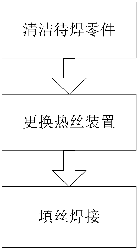
[0018] Step 1. Clean the parts to be welded. Clean the surface of the parts to be welded and the position of the butt joint to avoid residual impurities or pollutants in the gap;

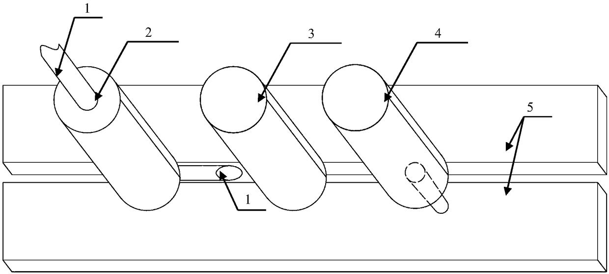
[0019] Step 2: Replace the heating wire device 2. Measure the gap of parts 5 to be welded, and replace the hot wire device 2 according to the gap to meet the filling requirements of the gap;

[0020] Step 3, filler wire welding. Align the hot wire 1 with the gap, start the welding machine, the hot wire 1 slowly fills the gap, and then the rolling stirring head 3 performs a rolling on the hot wire 1 and the parts to be welded, and then, the welding stirring head 4 pairs the hot wire 1 and the part 5 to be welded are subjected to f...


PUM


Abstract

The invention discloses a friction stir welding method for a hot wire. The friction stir welding method comprises the following steps: step 1, cleaning a part to be welded, specifically, cleaning thesurface and a butt-joint surface position of the part to be welded, and avoiding residual impurities or pollutants at a gap; step 2, replacing a hot wire device, specifically, measuring the gap of thepart to be welded, replacing a hot wire device according to the gap, and meeting the filling requirement of the gap; step 3, filling the heated welding wire into the gap position of a welding joint of the part to be welded through a special hot wire filling device; carrying out primary stir extrusion on the filled hot wire through a rolling stir head, and promoting preliminary plastic bonding forthe hot wire and base metal; and carrying out friction stir on the hot wire subjected to the primary stir extrusion and the base metal through a welding stir head, promoting plastic migration and dynamic recrystallization between the hot wire and the base metal, realizing metallurgical bonding for the hot wire and the base metal, and completing friction stir welding for the part under a large-gapcondition. The large-gap condition refers specifically to that h is not less than 0.5d and not greater than 1.25d, wherein h is the width of the gap, and d is the thickness of the part.

Description

technical field [0001] The invention relates to the field of friction stir welding, in particular to a hot wire friction stir welding method. Background technique [0002] After more than 20 years of development, the friction stir welding technology has become increasingly mature, and the technology has included many technologies such as retraction friction stir welding, static shoulder friction stir welding, double rotation friction stir welding, and double shoulder friction stir welding. Welding materials are also expanded from non-ferrous metals such as aluminum alloys, copper alloys, and titanium alloys to ferrous metals such as steel and metal matrix composites. However, the development of the above-mentioned technologies and the expansion of the scope of applicable materials have not expanded the welding ability of friction stir welding under the condition of large gaps. Currently, friction stir welding is carried out under the premise of strictly controlling the gaps ...

Claims


Application Information

Patent Timeline
Patent Type & Authority Applications(China)
IPC IPC(8): B23K20/12B23K20/24
CPCB23K20/12B23K20/24
Inventor 宋学成曹晓徐文豪徐耀钟尹玉环崔凡徐奎汤化伟李丹黄征
Owner SHANGHAI AEROSPACE EQUIP MFG GENERAL FACTORY
Why Eureka
Try Eureka