
Processing method of gear reducer

A technology of gear reduction box and processing method, which is applied in the direction of belt/chain/gear, transmission box, elements with teeth, etc., can solve the problem of easy deformation, equipment status and personnel status, gear box production efficiency and yield can not be satisfied Production requirements and other issues to achieve the effect of improving processing efficiency and reducing the accumulation of machine tool system errors

Inactive Publication Date: 2011-02-16
CRRC CHANGCHUN RAILWAY VEHICLES CO LTD
View PDF5 Cites 15 Cited by
  • Summary
  • Abstract
  • Description
  • Claims
  • Application Information

AI Technical Summary

Problems solved by technology

[0002] During the production process of 217 subway cars in Iran, the gear reduction box is a large thin-walled irregular cast steel box. Due to the influence of factors such as gearbox, the production efficiency and yield of the gearbox cannot meet the requirements of production, it is necessary to have a set of reasonable processing technology plan to overcome the various unfavorable factors in production, improve the processing quality of the gearbox and improve the production efficiency

Method used


Image

  • Processing method of gear reducer
  • Processing method of gear reducer
  • Processing method of gear reducer

Examples


Embodiment Construction

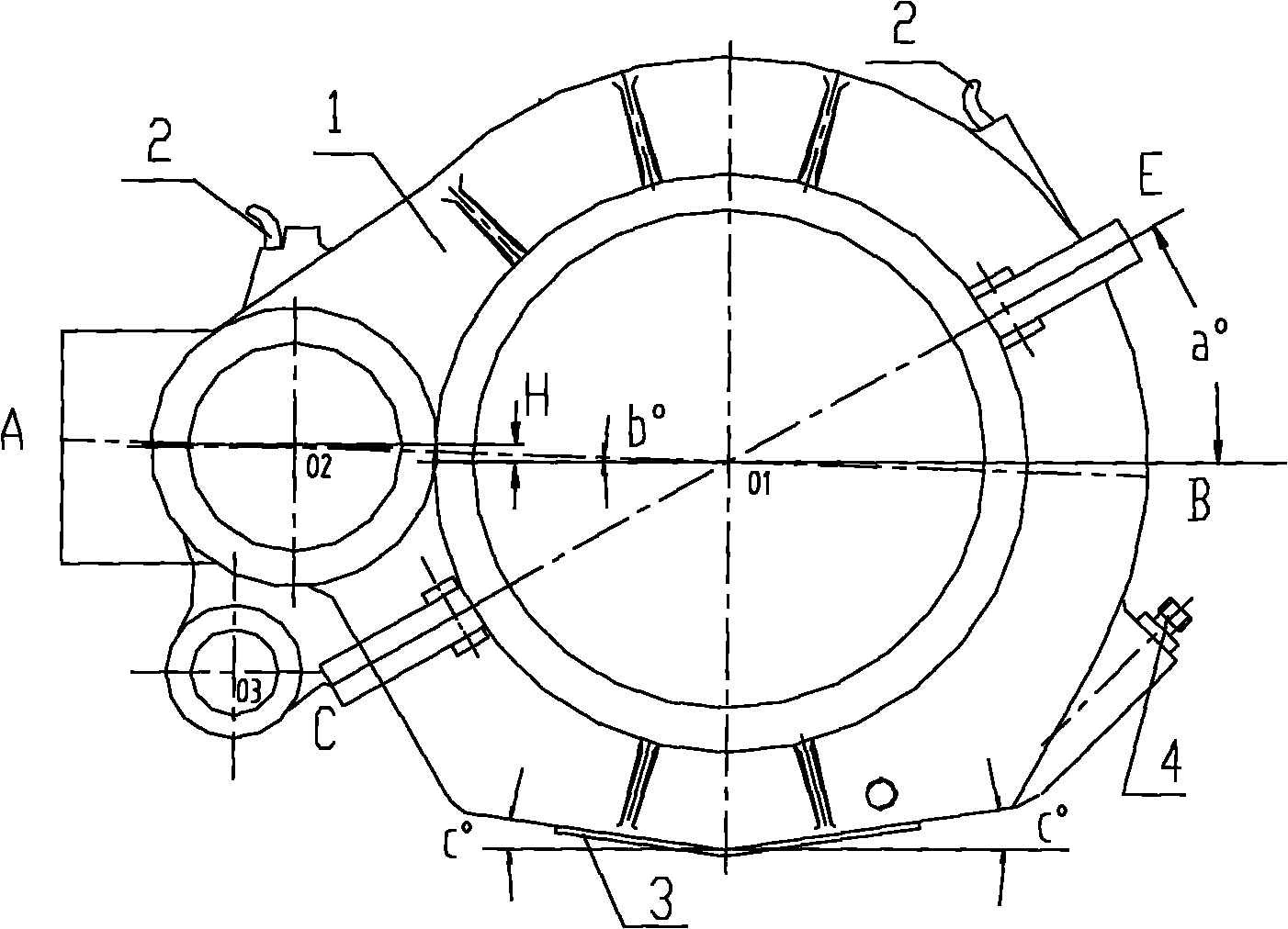
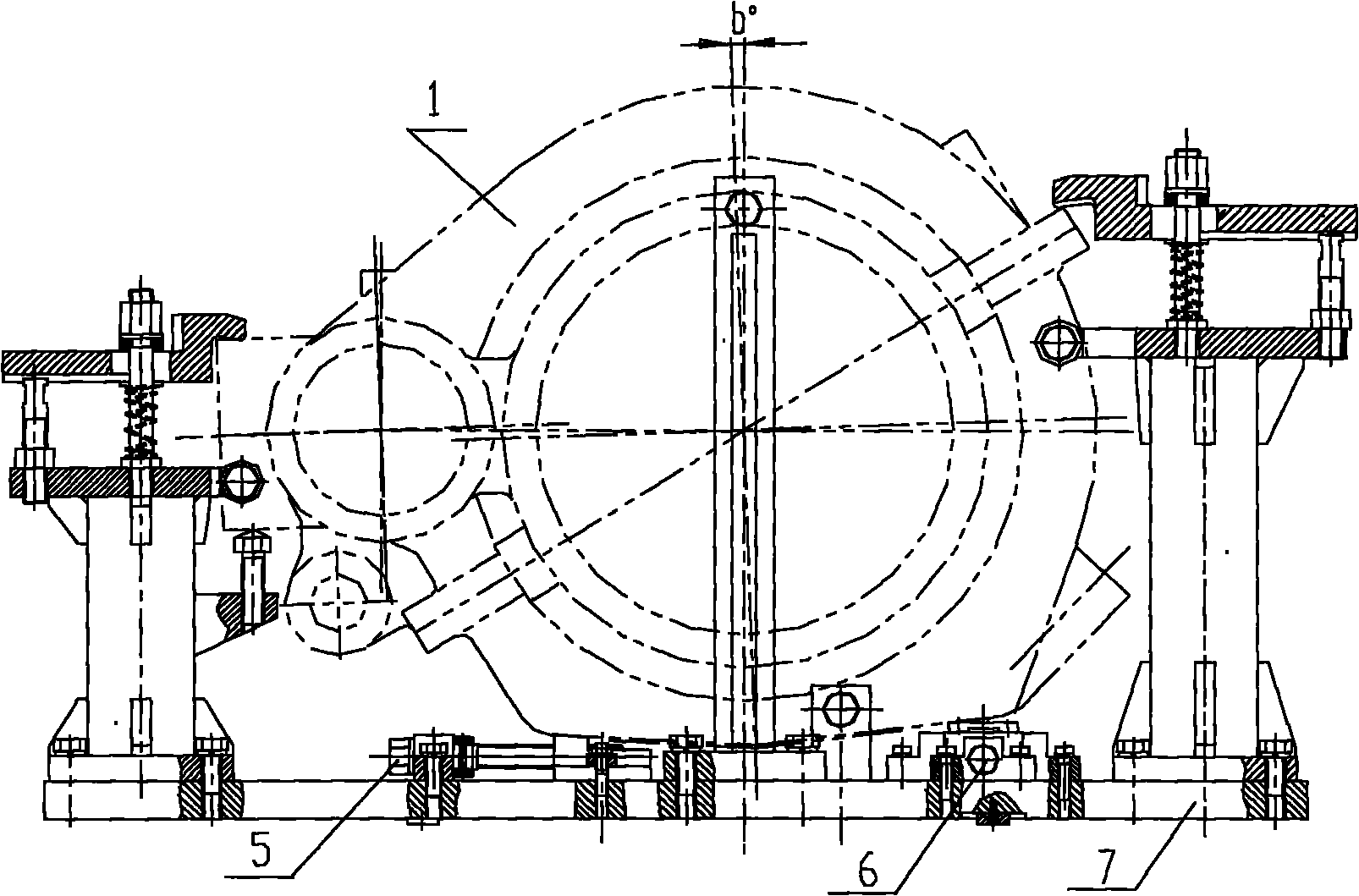
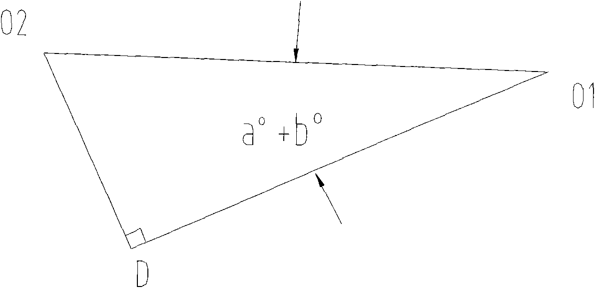
[0021] 1. Reference figure 1 , image 3 , Figure 9 , use the adjustable top 18 in the center support plate to fix the center support plate 19 in the driving gear hole and the driven gear hole of the gear reduction box, and draw the driving gear hole with the planning plan based on the outer wall of the driving gear hole of the gear reduction box Center O 2 . Then use the dash template O 2 o 1 D Draw out the center of the driven gear hole of the gear reducer O 1 , O 1 D must be separated from the gearbox surface C O 1 E is aligned. The marking template can pass through the center of the driving gear hole O 2 To the gearbox side C O 1 E makes a vertical line O 2 D, angle C O 1 o 2 Equal to a°+b°, the overall rotation angle b° of the gearbox can pass through the vertical distance H and the center distance O between the centers of the driving gear hole and the driven gear hole 2 o 1 It is calculated that sin b°=H / O 2 o 1 . Then connect the line O between the cen...


PUM


Abstract

The invention relates to a processing method of a gear reducer. The method comprises the following steps of: firstly, scribing the center O2 of a driving gear hole by utilizing a central supporting disk and a centre gauge and using the outer wall of the driving gear hole of a gear reducer as a reference, scribing the center O1 of a driven gear hole of the gear reducer with a scribing template and the central supporting disk, then, prolonging a center connecting line O2O1 of the driven gear hole and the driving gear hole to a point (A) and a point (B) at both ends of the gear reducer body and punching points so as to conveniently calibrate a scribing line; hoisting the gear reducer on a processing clamp, wholly rotating the gear box through the up-and-down movement of a left adjustable support and a right adjustable support so that the center O2 of the driving gear hole and the center O1 of the driven gear hole are connected into a horizontal line, wherein the connecting line is horizontal to a worktable of a machine tool; and roughly processing all parts of a gearbox, processing the surfaces and the holes of a handle, a soleplate, an oil neilsbed, welding, processing and finely processing the driving gear hole and the driven gear hole. The invention reduces error accumulation, comprehends the processing accuracy and processes the gear reducer by utilizing traditional equipment to improve the processing efficiency of the gear reducer and ensure the processing pass rate over 90 percent.

Description

technical field [0001] The invention belongs to the technical field of tooling technology for mechanical parts, and discloses a processing technology for a gear reduction box. Background technique [0002] In the production process of 217 subway cars in Iran, the gear reduction box is a large thin-walled irregular cast steel box. Influenced by other factors, the production efficiency and yield of the gearbox cannot meet the requirements of production, so it is necessary to have a set of reasonable processing technology plan to overcome various unfavorable factors in production, improve the processing quality of the gearbox and improve production efficiency . Contents of the invention [0003] The technical problem to be solved by the present invention is to provide a gear reduction box processing technology, without increasing the production cost, use the existing equipment to complete the hole system processing of the gear reduction box, improve the processing efficiency...

Claims


Application Information

Patent Timeline
Patent Type & Authority Applications(China)
IPC IPC(8): B23P15/00
CPCB23P15/00F16H57/022F16H57/02Y10T29/49826
Inventor 刘孝峰
Owner CRRC CHANGCHUN RAILWAY VEHICLES CO LTD
Learn More