
Floor cutting machine

A technology for cutting machines and floors, which is applied in slotting machines, mortising machines, metal processing, etc., and can solve problems such as unhealthy operators, pollution of the operating site, and cumbersome operations.

Inactive Publication Date: 2011-02-16
向广宏
View PDF6 Cites 2 Cited by
  • Summary
  • Abstract
  • Description
  • Claims
  • Application Information

AI Technical Summary

Problems solved by technology

Moreover, when the floor is installed, it is necessary to slot on site. The existing cutting machine does not have such a function, and it needs to rely on a special slotting machine to slot, which is not only cumbersome to operate but also wastes time. A lot of dust will be generated during use, which is not good for the health of the operator, and will also cause certain pollution to the operating site.

Method used


Image

  • Floor cutting machine
  • Floor cutting machine
  • Floor cutting machine

Examples


Embodiment Construction

[0023] In the following, the present invention will be further described through the description of specific embodiments with reference to the accompanying drawings.

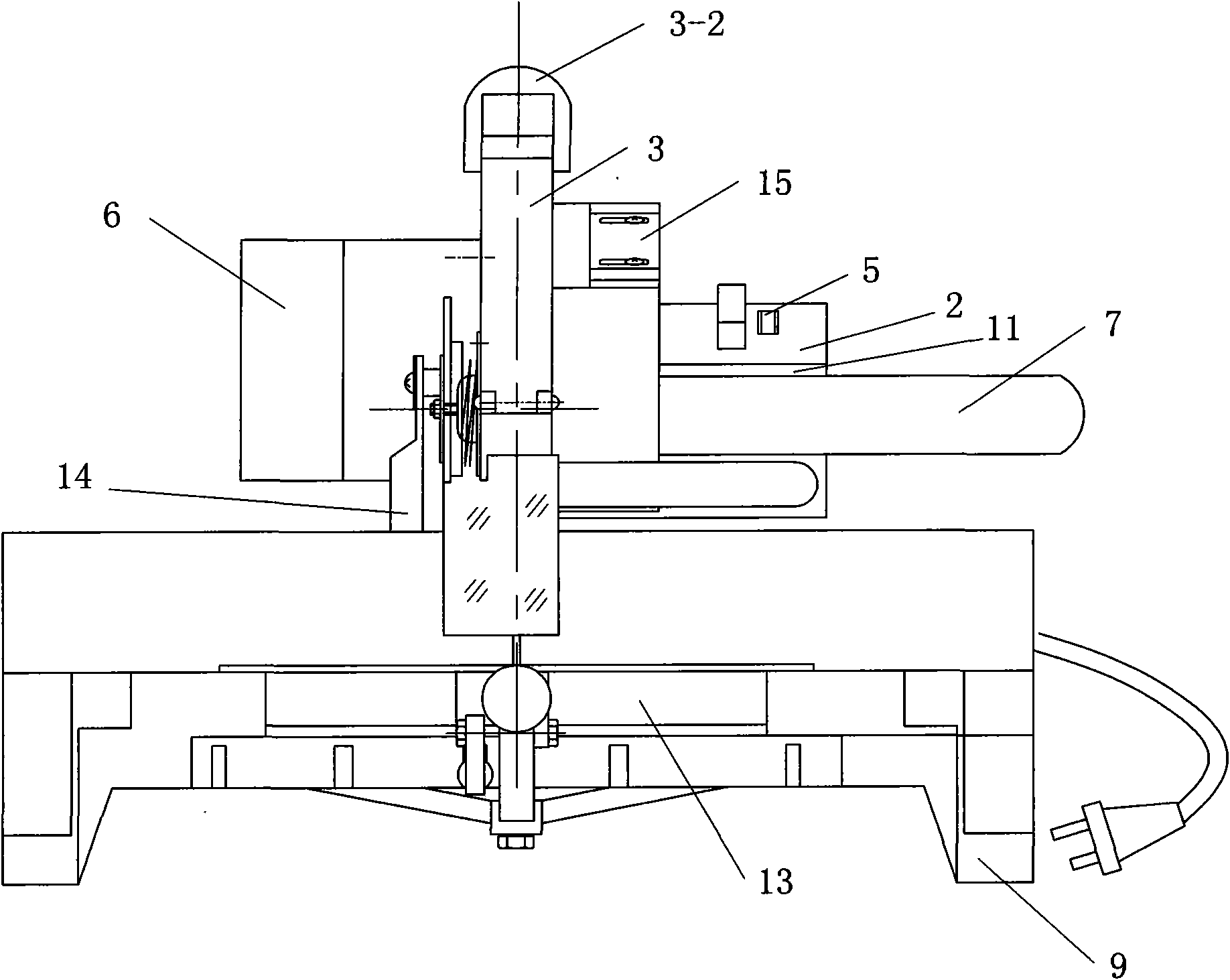
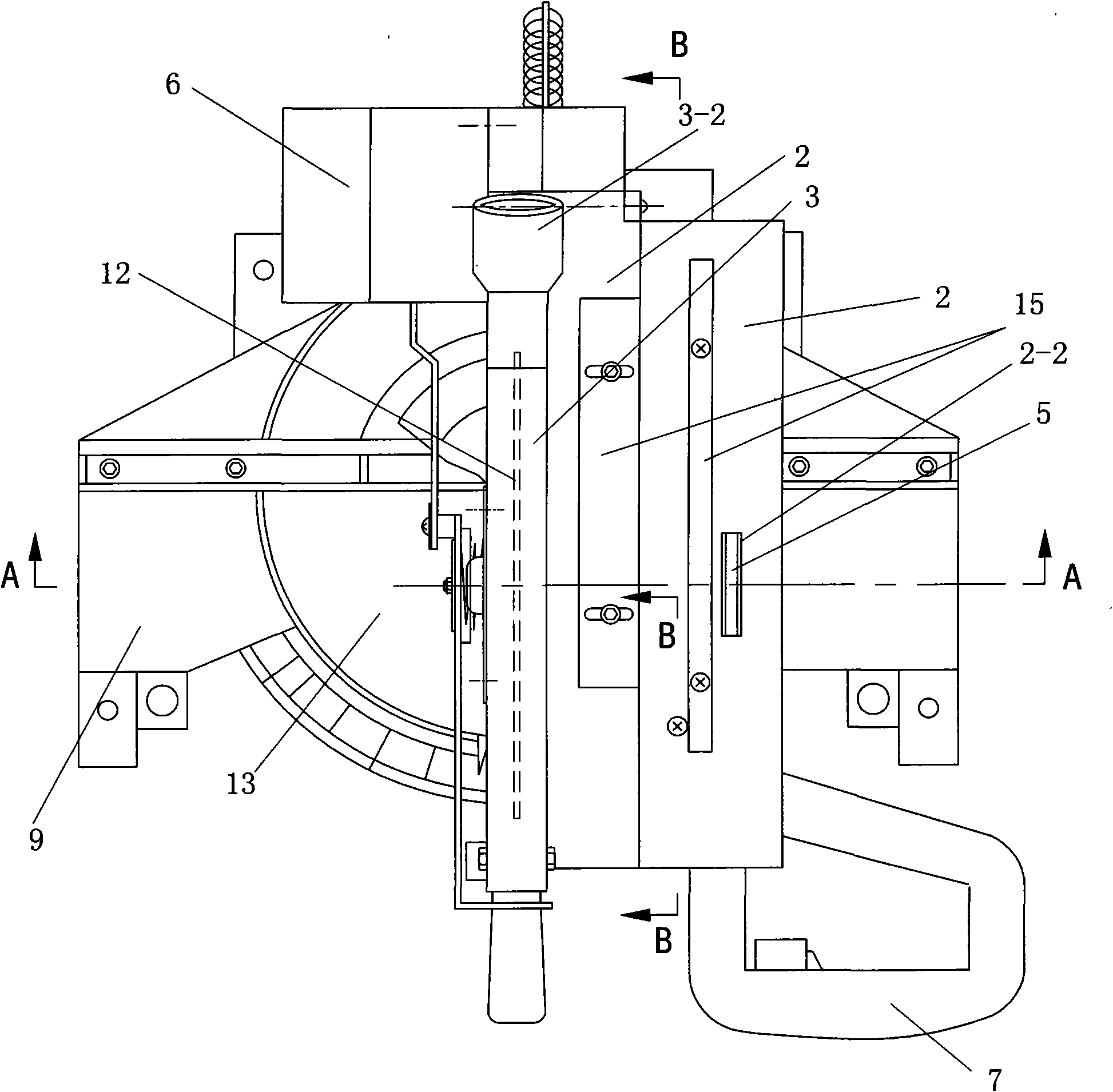
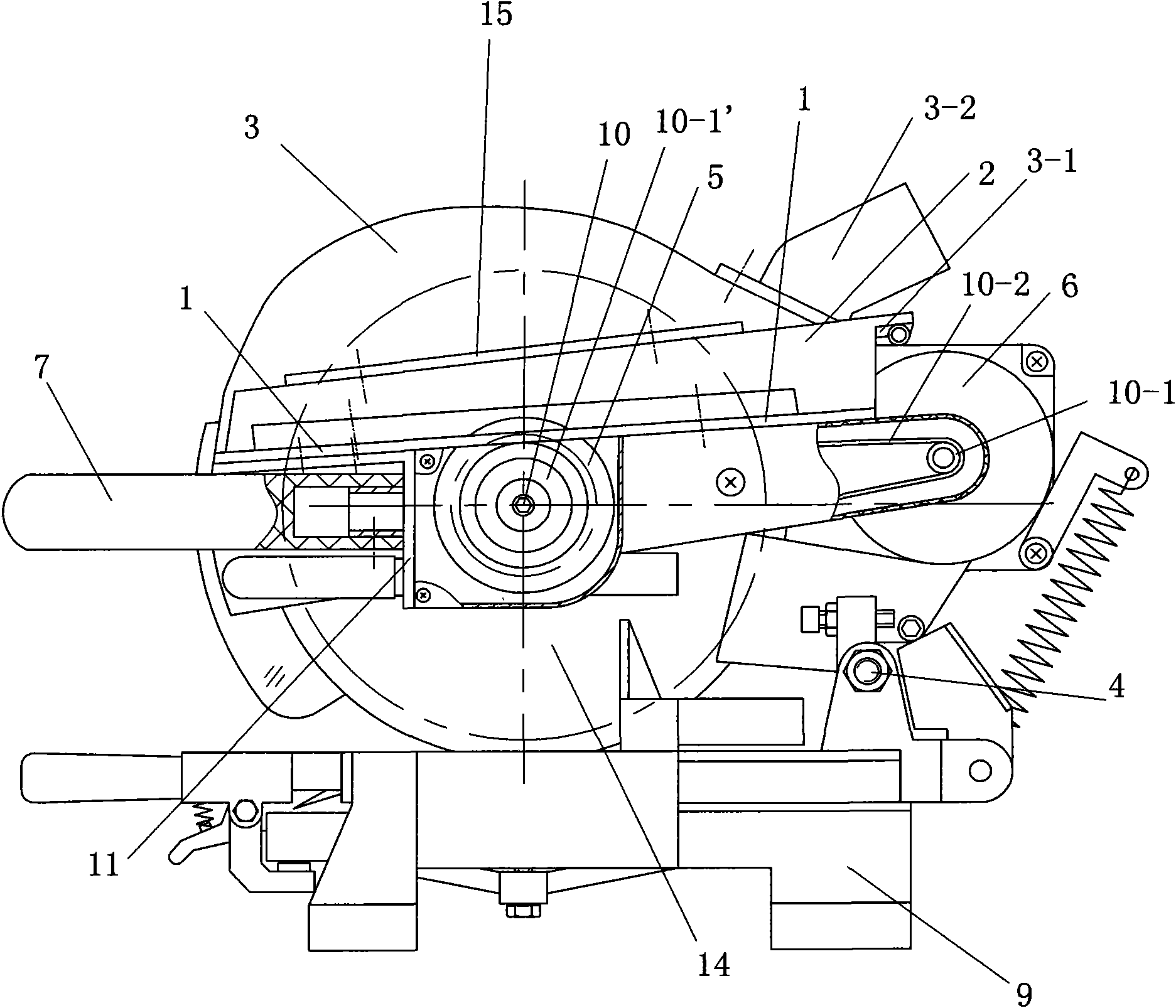
[0024] Such as Figure 1-11 As shown, a floor cutting machine includes a base 9, a motor 6, a fuselage 14 and a main shaft 10, the fuselage 14 is hinged on the base 9 through a hinge shaft 4, and the main shaft 10 is rotatably connected to the fuselage 14 Above, the main shaft 10 is fixedly connected with a saw blade 12, one end of the main shaft 10 is also fixedly connected with a pulley 10-1', the motor 6 is fixed on the body 14, and the output shaft of the motor is fixedly connected with a pulley 10-1, and the motor 6 passes through The belt 10-2 and the pulleys 10-1, 10-1' are connected in transmission with the main shaft 10, and the main shaft 10 is also fixedly connected with a slotted saw blade 5; The board 2 is provided with a saw blade groove 2-1, the top of the saw blade 12 exposes the saw blade groov...


PUM


Abstract

The invention discloses a floor cutting machine which comprises a base, a motor, a machine body and a main shaft, wherein the machine body is hinged on the base through a hinge support shaft, the main shaft is rotatably connected to the machine body and is fixedly connected with a saw blade, one end of the main shaft is also fixedly connected with a belt wheel, the motor is fixed on the machine body, a motor output shaft is fixedly connected with the belt wheel, the motor is in transmission connection with the main shaft through a belt and the belt wheel, the main shaft is also fixedly connected with a slotting saw blade; a cutting bedplate is arranged on the machine body and provided with a saw blade slot and a slotting saw blade slot, the top of the saw blade exposes out of the saw blade slot, the top of the slotting saw blade exposes out of the slotting saw blade slot; a saw blade upper protective shield covers the saw blade; one end of the protective shield above the saw blade is articulated with the cutting bedplate, and the other end is fixedly connected with the cutting bedplate through a lock catch; and the machine body is also fixedly connected with a handle. The invention has the characteristics of being capable of longitudinally cutting a long material and slotting.

Description

technical field [0001] The invention relates to a cutting device, in particular to a floor cutting and floor slotting device. Background technique [0002] The fuselage of the existing floor cutting machine is hinged on the base, and the saw blade installed on the fuselage presses down on the fuselage to cut the material. Due to the limitation of the base, often long materials cannot be cut longitudinally, and can only be cut. The cutting head is a short length, and in actual operation, the floor is all long strips, and it needs to be cut into materials of different widths for on-site assembly when installing the floor. Moreover, when the floor is installed, it is necessary to slot on site. The existing cutting machine does not have such a function, and it needs to rely on a special slotting machine to slot, which is not only cumbersome to operate but also wastes time. A lot of dust will be generated during use, which is not good for the health of the operator, and also cau...

Claims


Application Information

Patent Timeline
IPC IPC(8): B27F5/02B26D3/06
Inventor 向广宏
Owner 向广宏
Learn More