
Asphalt crack pouring device for cement road paving

A road and asphalt technology, which is applied in the field of asphalt joint filling devices for paving cement roads, can solve the problems of time-consuming, time-consuming and labor-intensive projects, and shorten the construction period, etc., and achieve the effects of centralized and simple procedures, improved work efficiency, and fast and rapid construction

Active Publication Date: 2019-08-20
深圳市盛通万虹科技有限公司
View PDF7 Cites 3 Cited by
  • Summary
  • Abstract
  • Description
  • Claims
  • Application Information

AI Technical Summary

Problems solved by technology

[0004] The existing joint filling needs to be completed through multiple processes, and the project takes a lot of time, which is not conducive to shortening the construction period and is time-consuming and laborious

Method used


Image

  • Asphalt crack pouring device for cement road paving
  • Asphalt crack pouring device for cement road paving
  • Asphalt crack pouring device for cement road paving

Examples


Embodiment 1

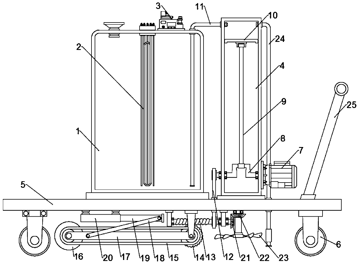
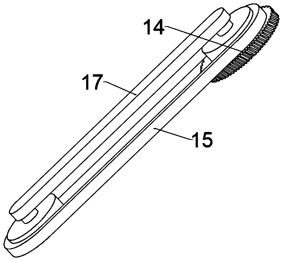
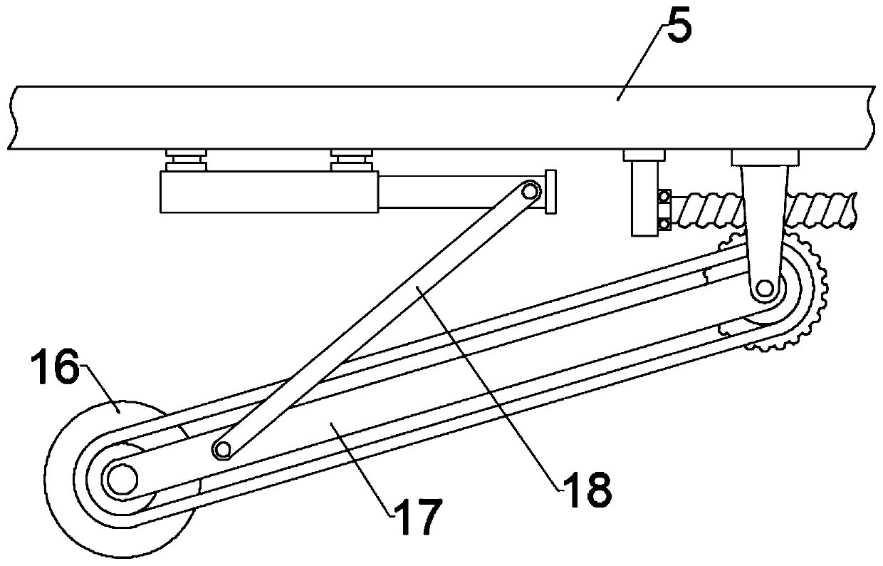
[0022] see Figure 1~3 , in an embodiment of the present invention, an asphalt joint filling device for paving cement roads, comprising a heating barrel 1 fixed on a bottom plate 5, a liquid pumping tank 4 positioned on one side of the heating barrel 1, and a cutting tool for slit cement road surface Components; wherein, a hopper for injecting asphalt is fixed through the top of the heating barrel 1, and an electric heater 2 with a signal connection controller 3 and a power supply is fixed inside the heating barrel 1, and the heating barrel 1 and the pumping tank 4 pass through The liquid pipe 11 is connected, and a one-way valve is arranged at the upper mouth of the liquid inlet pipe 11, and the upper part of the liquid pumping tank 4 is connected to and fixed on the liquid outlet pipe 24, and the asphalt in the heating barrel 1 is heated by the electric heater 2 , keep it in a flowing liquid state, and utilize the pumping tank 4 to pour the asphalt in the heating barrel 1 in...

Embodiment 2

[0027] Obviously, there will inevitably be dust on the ground seam cut out, therefore, in order to pour asphalt into the ground seam better, a blower assembly is also provided under the bottom plate 5, specifically, the blower assembly includes The bevel gear set at the end, the bevel gear set is composed of the first bevel gear 21 fixed on the end of the worm 13 and the second bevel gear 22 fixed on the rotating shaft, the first bevel gear 21 meshes with the second bevel gear 22, and the rotating shaft The upper end is rotatably connected to the bottom plate 1, and the lower end of the rotating shaft is fixed with a fan blade 23. The rotating worm 13 drives the rotating shaft to rotate through the bevel gear set, thereby realizing the driving of the fan blade 23 to rotate and blow air, and achieve the integrated function of cutting, blowing, and filling seams;

[0028] The lower corners of the base plate 5 are all rotatably provided with rollers 6, and the top of the rear port...


PUM


Abstract

The invention discloses an asphalt crack pouring device for cement road paving, and particularly relates to a device that a crankshaft drives a piston plate to do reciprocating vertical motion througha connecting rod to achieve a material pumping function, and a rotating worm drives a worm gear and a cutter to rotate to achieve a crack cutting function. The problems that existing crack pouring needs to be completed through multiple devices and multiple processes, and time and labor are wasted are solved. A signal connection controller and an electric heater of a power supply are fixed to theinterior of a heating barrel, the heating barrel communicates with a liquid suction tank through a liquid inlet pipe, a one-way valve is arranged at an upper opening of the liquid inlet pipe, and theupper portion of the back portion of the liquid suction tank communicates with and is fixedly provided with a liquid outlet pipe; and a cutting assembly comprises a swinging rod of which one end is rotatably arranged under a bottom plate, the cutter rotatably arranged at the other end of the swinging rod, the worm gear arranged at the rotating center of the swinging rod and the bottom plate and the worm rotatably connected below the bottom plate, the worm meshes with the worm gear, and the worm gear is connected with the cutter through a second transmission part.

Description

technical field [0001] The invention relates to a road laying machine, in particular to an asphalt joint filling device for cement road laying. Background technique [0002] When laying roads, especially cement roads, it is often necessary to cut and pour asphalt into the formed road surface. The general process of asphalt filling joints is four steps: slotting, cleaning, heating, filling joints, and opening traffic. [0003] Firstly, the slotting process uses a slotting machine for slotting, which needs to be used to cut the road surface; then it is cleaning, using a fire-fighting fan or a backpack fan to remove the dust in the opened slot; and then heating Heating refers to heating the pavement to be filled before filling the joint to make the joint glue and the original road surface have better bonding performance; the last is the joint filling, which is the key to the whole project. [0004] Existing joint filling needs to be completed through multiple processes, and th...

Claims


Application Information

Patent Timeline
Patent Type & Authority Applications(China)
IPC IPC(8): E01C23/09E01C19/08
CPCE01C19/08E01C23/096
Inventor 刘加华
Owner 深圳市盛通万虹科技有限公司
Learn More