Angle-adjustable printing screen and angular adjusting device thereof

An angle adjustment device, a technology for printing screen, applied in printing, printing machine, rotary printing machine and other directions, can solve the problems of low precision, difficult to meet requirements, etc., and achieve the effect of improving precision

Active Publication Date: 2012-01-11
SUZHOU MAXWELL TECH CO LTD
View PDF4 Cites 0 Cited by
  • Summary
  • Abstract
  • Description
  • Claims
  • Application Information

AI Technical Summary

Problems solved by technology

[0004] In order to solve the defects of low accuracy and difficulty in meeting the requirements of the printing screen in the prior art, a device for adjusting the angle of the printing screen is provided, including a base, a printing screen frame, and a power supply. The motor and the transmission mechanism also include an arc-shaped guide rail and a guide rail slider fixed thereon, a grating ruler and a reading head thereof, the arc-shaped guide rail is fixed on the base, and the printing screen frame and the guide rail The slider is fixedly connected, the grating ruler is installed on the printing screen frame, the reading head is installed at a certain distance close to the grating ruler, and the transmission mechanism is connected with the motor and the screen frame respectively

Method used


Image

  • Angle-adjustable printing screen and angular adjusting device thereof
  • Angle-adjustable printing screen and angular adjusting device thereof
  • Angle-adjustable printing screen and angular adjusting device thereof

Examples


Embodiment 1

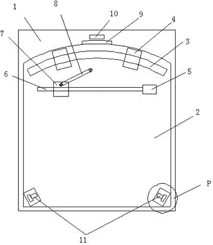
[0024] Install a section of arc guide rail on the edge of the part that needs to make angular movement, and then use a connecting rod to drive a point close to the moving part of the arc guide rail, so that the moving part can make angular movement around the center of the arc guide rail along the arc guide rail. We call this driving method the edge driving method.

[0025] If the center drive method is adopted (that is, the force application point of the drive motor is set at the center of the rotating part), usually the center rotating motor has 10,000 pulses per revolution, and there is an error of about 1 pulse per revolution on average, then the resulting angle error For: 1 / 10000=3.6*10 -2 Spend. In this embodiment, we use the same printing screen and rotary table, the radius of the arc guide rail used is 300mm, and the minimum reading of the grating scale used is 1 μm, then the angular error generated at this time is: (1 / 2*3.14 *300*103)*360=1.9*10 -4 Compared with...

Embodiment 2

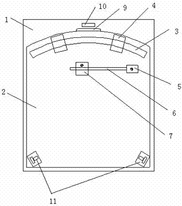
[0031] Such as image 3 As shown, the difference between this embodiment and Embodiment 1 is that the transmission mechanism does not include the drive link 8 in Embodiment 1, but only consists of a lead screw 6 and a lead screw nut 7 thereof, and the lead screw nut 7 can be Change its position on the described leading screw 6 along with the rotation of leading screw 6, and the two ends of described leading screw 6 are connected with described motor 5 and wire mesh frame 2 in rotatable manner respectively, and described motor 5 can It is connected to the base 1 in a rotating manner. When the lead screw 6 rotates under the drive of the motor 5, the transmission mechanism composed of the lead screw 6 and its lead screw nut 7 drives the wire mesh frame 2 to rotate along the track of the arc track, and the motor 5 also surrounds it on the base 1 A fixed point rotation on . Since the screw nut 7 is running in a straight line, the angle of the screw 6 will change at any time, ...


PUM


Abstract

The invention relates to a device for adjusting the angle of a printing screen, which comprises a base, a printing screen rack, a motor and a transmission mechanism for supplying power, an arc guide rail, a guide rail sliding block fixed on the arc guide rail, a grating ruler and a reading head thereof, wherein, the arc guide rail is fixed on the base; the printing screen rack is fixedly connected with the guide rail sliding block; the grating ruler is arranged on the printing screen rack; the reading head is arranged at the base close to the grating ruler at certain distance; and the transmission mechanism is connected with the motor and the screen rack respectively. In the invention, by combination of the arc guide rail, the grating ruler and the reading head thereof, measurement and control of angular movement are skillfully changed into measurement and control of the arc distance away from the rotation center from the rotation angle; and measure and control precision is greatly improved by virtue of the radius amplification effect.

Description

technical field [0001] The invention relates to printing equipment used in the manufacture of monocrystalline silicon and polycrystalline silicon solar cells, in particular to a printing screen and a device for adjusting its angle. Background technique [0002] In order to print electrodes on the front side of the silicon wafer, after the silicon wafer is positioned on the workbench, the position of the silver grid line needs to be adjusted. A method of overprinting the front electrode twice has become popular in the industry. The two overprints increase the thickness of the front electrode without increasing the width of the electrode, which increases the efficiency of the cell by about 0.5%. The technical difficulty is that dozens of silver grid lines with a width of about 100 microns will be printed Twice, the deviation of these two printing overprints is preferably less than 1 micron, which poses a great challenge to the previous printing deviation (generally acceptable ...

Claims


Application Information

Patent Timeline
Patent Type & Authority Patents(China)
IPC IPC(8): H01L31/18B41F15/36
CPCY02P70/50
Inventor 施政辉王正根
Owner SUZHOU MAXWELL TECH CO LTD
Why Eureka
Try Eureka